00191457-02.pdf - 第27页
Retrofit instructions Nozzle changer SIPLACE HS-50 / HS-60 / D4 06/2006 Edition 27 2 Fig. 2 - 7 Magazine and nozzle garages (1) Positioning fiducial (2) Locking pla te (3) Nozz le garage (4) Hole for the pa rallel pin (7…

Retrofit instructions Nozzle changer SIPLACE HS-50 / HS-60 / D4
06/2006 Edition
26
: Check the address set for CAN I/O module 3: address: 294H
Plug number Jumper
X19 No
X20 Yes
X21 No
X22 No
X23 No
2.10 Settings
: Switch on the placement system.
: Press the Start button when you see the prompt.
: Configure the nozzle changer in the line computer configuration editor.
: Use the SITEST program to calibrate each nozzle changer.
: Determine the z height for each magazine.
2.11 Commissioning the nozzle changer
: When you fill a magazine with a certain nozzle type for the first time, attach an adhesive label
to identify the type.
2
Only ONE nozzle type must be used in each magazine.
Fill the magazines off the machine and always replace complete magazines. 2
2
: Open the locking plate and place the nozzles in the nozzle garages.
: Close the locking plate so that the nozzles cannot drop out of the magazines.
2
Before you fill magazine, make sure that all the nozzles on the revolver head have been returned
to their magazines. 2
2
2
: Do not allow components to drop onto the magazines. If they do, they could jam the locking
plate.
: Do not allow components to drop onto free feeder module locations because they will stick to
the magnetic bar. Production may have to be interrupted if the feeder modules are not placed
on the component table correctly. You should therefore regularly clean the magazines and free
locations.
Retrofit instructions Nozzle changer SIPLACE HS-50 / HS-60 / D4
06/2006 Edition
27
2
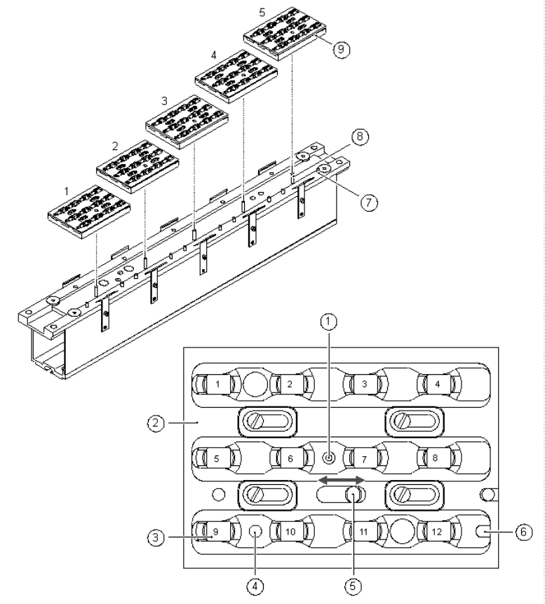
Fig. 2 - 7 Magazine and nozzle garages
(1) Positioning fiducial
(2) Locking plate
(3) Nozzle garage
(4) Hole for the parallel pin (7) for centering the magazines
(5) Hole for the parallel pin of the slide mechanism
(6) Slot for the parallel pin (7) for centering the magazines
(7) Parallel pin for centering the magazines
(8) Parallel pins for opening and closing the locking plate
(9) Magazines
Retrofit instructions Nozzle changer SIPLACE HS-50 / HS-60 / D4
06/2006 Edition
28
2.12 Installing the 2nd nozzle changer
Fig. 2 - 3 shows the locations for installing the first and second nozzle changer for each gantry .2
: Detach the plug from the y-adapter on the blue compressed air line.
: Before installation, position the nozzle changer (item 1 to 4 in Fig. 2 - 1) so that the opening for
the electrical and pneumatic connections at the bottom (item A in Fig. 2 - 1) is pointing in the
direction shown in Fig. 2 - 1.
: Plug the control cable (item 9 in Fig. 2 - 3 into the control board and secure in place with the
two screws.
The assignment of control cables to nozzle changers is shown in table 2 - 1.
: Make sure that the contact surface (item 8 in Fig. 2 - 3) for the nozzle changer on the used tape
guide channel is clean.
: Place the nozzle changer (item 5 in Fig. 2 - 3) on the used tape guide channel (item 1 in Fig.
2 - 3) at the point indicated by with item 8 in Fig. 2 - 3.
: Start by loosely tightening the four M4 x 16 hexagon socket-head screws (item 6 in Fig. 2 - 3).
: Then fully tighten the four M4 x 16 hexagon socket-head screws in a diagonally opposite se-
quence.
: Attach the blue compressed air hose of the nozzle changer to the y-adapter.
: Check the connectors of the CAN I/O module 3 in sector distributor 1 (see section 2.9.
: Make the settings described in section 2.10.
: Commissioning the nozzle changer (see section 2.11).
2
2
2
2
2