YG200L_khm_Eg.pdf - 第3页
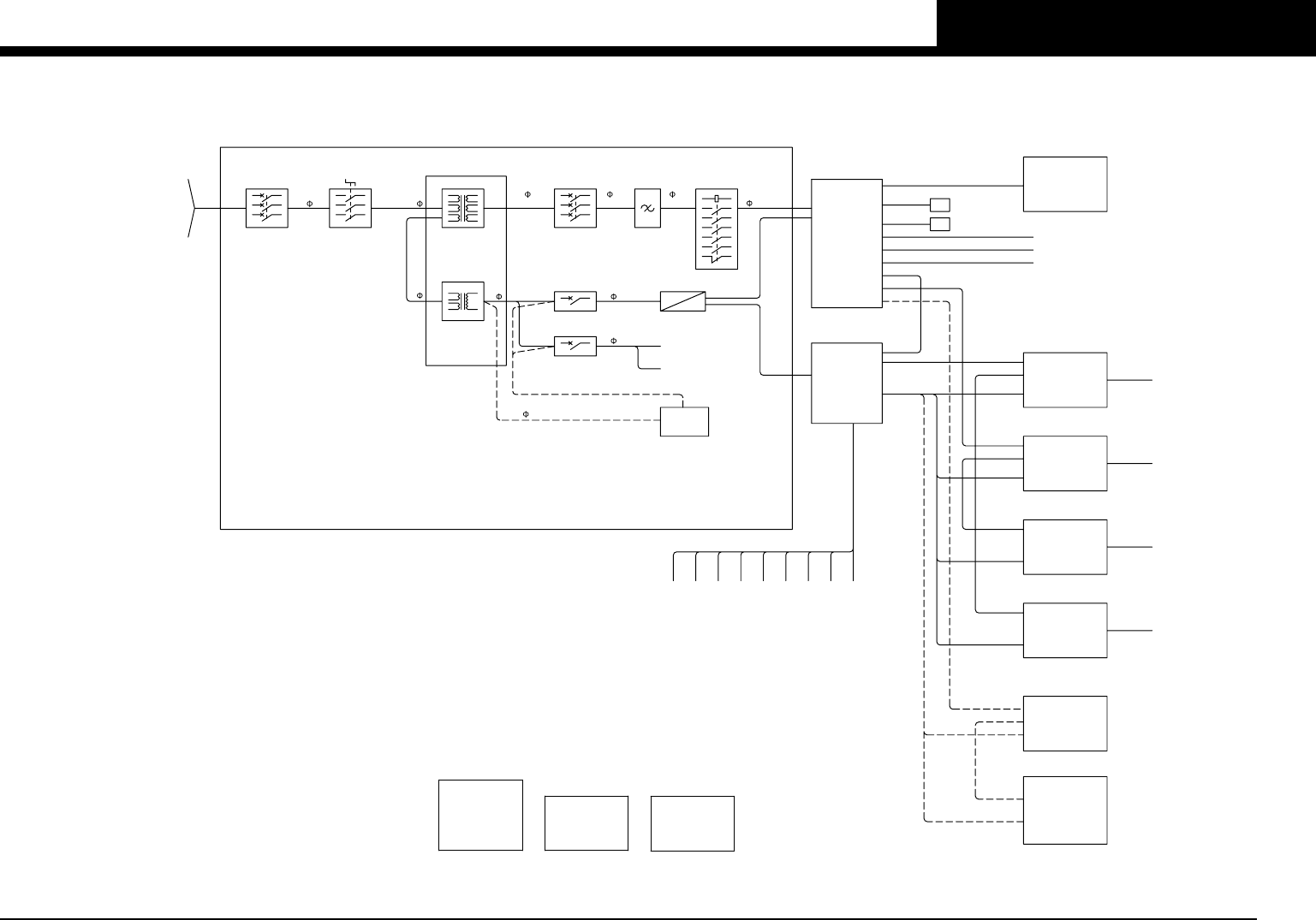
YG200L (KHM) Over view Control box I/O conveyor board -1- I/O conveyor board -2- I/O conveyor board -3- I/O head front A (HEAD A) I/O head front B (HEAD B) I/O head rear A (HEAD C) I/O head rear B (HEAD D) Operation pane…
Safety.
To replace the purchased parts safely, be sure to comply with the following items.
However the following cannot cover all items regarding safety in detail. So it is
extremely important that the worker or person handling the machine make correct
decisions regarding safety.
CAUTION Machine operation of operator•Work is limited to maintenance and
safety skill.
Besuretoturnothemachine’spowersupplybeforedoingtheexchangework.
Be sure to push the emergency stop SW, and do adjustment work under the
emergency stop condition.
Refer to the manual for the replacement work of each consumable part.
*
Safety alert symbols and signal words
CAUTION
Indicates a potentially hazardous situation which, if not avoided, may result in minor
injury, or material loss or damage to the machine. These points are important for
protecting the safety of the machine and data, etc.
安全について
お買い上げいただいたパーツを安全に交換していただくために、下記の事項は必ず守って作
業を行ってください。しかしながら、下記に全ての安全性に関する項目を細部にわたり網羅
することは困 難です。 従って作業 者自身 の安 全に対 する正確な判 断が 非常に 大切な要素とな
りま すことをご 留意ください。
注意 作業者は本機の動作・メンテナンスに習熟していて安全に作業を行える方に限り
ま す。
① 交換作業は、マシンの電源を切ってから必ず行ってください。
②調整作業は、非常停止 SW を押し、非常停止状態で必ず行ってください。
③ 消耗品の交換、 各メンテナンス作業についてはマニュアルをご参照ください。
※安全標記の 注意は取り扱いを誤った場合、傷害に至る可能性または物的損害の発生
が想定される内容を示しています。本体およびデータなどの損傷を防ぐために重要な注
意 事 項 で す。
YG200L (KHM)
Over view
Control box
I/O conveyor board -1-
I/O conveyor board -2-
I/O conveyor board -3-
I/O head front A (HEAD A)
I/O head front B (HEAD B)
I/O head rear A (HEAD C)
I/O head rear B (HEAD D)
Operation panel sel.
FIX24 feeder structure
FES24 feeder structure
FES20 feeder structure
FES20&24 safety circuit (non stop)
FES20&24 safety circuit (normal)
CLI FIX24 feeder structure
CLI FES24 feeder structure
CLI FES20 feeder structure
24 feeder indictor (option)
20 feeder indictor (option)
Power transformer terminal
Power circuit
Emergency circuit
Air circuit (YG200L SF)
Air circuit (YG200L SF&FES)
Air circuit (YG200L FNC)
Air circuit (YG200L FNC&FES)
Wiring parts list
Table of contents
Confi dential & Proprietary
P.1
P.2
P.3
P.4
P.5
P.6
P.7
P.8
P.9
P.10
P. 11
P.12
P.13
P.14
P.15
P.16
P.17
P.18
P.19
P.20
P.21
P.22
P.23
P.24
P.25
P.26
P.27
P.28
PAG E
1
YG200L (KHM)
Confi dential & Proprietary
KHM-000-CCV0
Over view
POWER TRANSFORMER
TERMIANL
OPERATION PANEL SEL.
COVER S/W
FRONT PANEL
AREA SENSOR
EMG S/W
VALVE
SIGNAL TOWER
CONVEYOR MOTOR
30W
SENSOR
OPERATION PANEL
FRONT PANEL
Each Cameras
Each Motors
FDD (OPTION)
USB MEMORY
INPUT:
AC50/60Hz 4.0A (MAX)
CONTROL: 1PH 100V
MOTOR: 3PH 220V
OUTPUT:
DRIVER
CONTROL BOX
AC50/60Hz 20A (MAX)
3:2.30KW (TOTAL)
1:3.24KW (TOTAL)
2:3.24KW (TOTAL)
3PH 200V 0~375Hz
Power Supply
GS21 DC24V 14A
Filter
Noise
NF11
AC220V
AC100V
DC24V
AC220V
33
1
1
1
1
AC100V
1
380/400/416V
200/208/220/240
3~50/60Hz
Rating 7.1KVA MAX.
Power consumption 1.1KW
AC100V
AC100V
LCD1
LCD2
UPS
(OPTION)
QF22 1A
Transformer
Transformer
Main Switch
QS11
Protector
Circuit
QF31 10A
QF21 7A
Contactor
KM10/KM10A
Main Breaker
QF11 20A
See Page 10
POWER CIRCUIT
TM11 3.56KVA
TC11 0.75KVA
See page 21
COMU
P21
HEAD SENSOR, VALVE
I/O HEAD FRONT A
DC24V
COMU
COMU
COMU
A1
See Page 2
I/O CONVEYOR
P25
See Page 3-5
See Page 6
P22
HEAD SENSOR, VALVE
I/O HEAD FRONT B
DC24V
COMU
COMU
See Page 7
P23
I/O HEAD REAR A
DC24V
COMU
HEAD SENSOR, VALVE
See Page 8
P24
I/O HEAD REAR B
DC24V
COMU
HEAD SENSOR, VALVE
See Page 9
FES20
FIX24 & FES24
DC24V
COMU
COMU
FEEDER INDICATOR
(OPTION)
COMU
COMU
FIX24
FES24
FES20
COMU
DC24V
CLI FEEDER (OPTION)
See Page 19
See Page 20
See Page 16
See Page 17
See Page 18
See Page 22
AC100V
NON STOP
NORMAL
FES20&24 SAFETY CIRCUIT
FEEDER STRUCTURE
See Page 11
FIX24
FES24
FES20
See Page 12
See Page 13
See Page 14
See Page 15
EMERGENCY CIRCUIT
See Page 23
3
AC220V
3
AC220V
3
3