00198377-01_SM_JTF-ML2_en.pdf - 第62页
3 Tower Mechanics 3.13 Removing the Dual Kicker and Dismantling Parts 62 Service Manual SIPLACE JTF-ML2 08/2017 3.13.3 Replacing the Dual Kicker Timing Belt Parts, Equipment and Tools ● Standard tools ● Dual kicker timin…
3 Tower Mechanics
3.13 Removing the Dual Kicker and Dismantling Parts
Service Manual SIPLACE JTF-ML2 08/2017 61
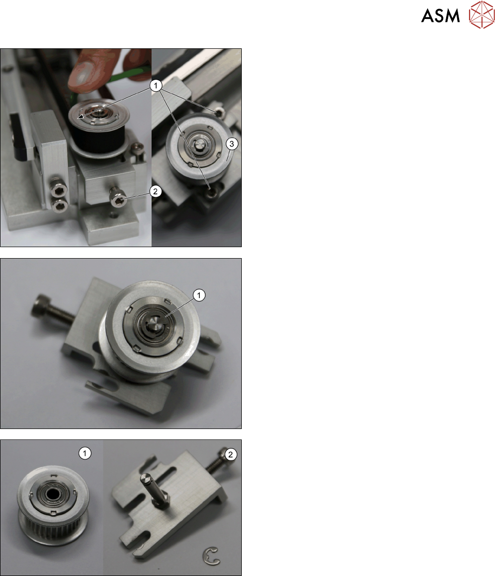
► Remove the two screws ISO 4762 - M 3 x 8-
A2-70 [03042542-xx] (1).
► Loosen the screw ISO 4762 - M 4 x 12-A2-70
[03042553-xx] (2).
► Remove the belt.
► Remove the Driven pulley w/ bearing [03148257-
xx] (3).
► Remove the Cantilever shaft w/thread ring groov-
HEX [03153305-xx] (1).
1. Driven pulley w/ bearing [03148257-xx]
2. Cantilever shaft w/thread ring groov-HEX
[03153305-xx]
Installation
► Follow the removal instructions in reverse order for installation.
3 Tower Mechanics
3.13 Removing the Dual Kicker and Dismantling Parts
62 Service Manual SIPLACE JTF-ML2 08/2017
3.13.3 Replacing the Dual Kicker Timing Belt
Parts, Equipment and Tools
●
Standard tools
●
Dual kicker timing belt [03153291-xx]
Removal
► Switch off the machine, disconnect it from the power supply and secure it to prevent
unauthorized reactivation. Observe the instructions in section 1.2 "Preparatory Work..." [}11].
► Remove the top cover (see 2.1.3 "Removing Tower Top Cover" [}25]).
► Follow the removal instructions as shown in 3.13 "Removing the Dual Kicker and Dismantling
Parts" [}57].
► Follow the removal instructions as shown in 3.13.2 "Replacing the Driven Pulley" [}60].
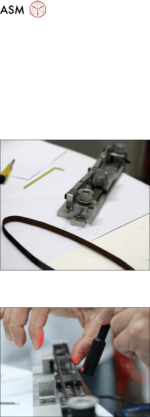
1. Dual kicker timing belt [03153291-xx]
2. Dual kicker [03155270-xx]
Installation
► Follow the removal instructions in reverse order for installation. Also observe the following in-
structions:
► Adjust the belt tension with the help of a belt ten-
sion measuring device to 109±5 HZ
► See also 3.13.5 "Final Steps Before Remounting the Kicker" [}66].
3 Tower Mechanics
3.13 Removing the Dual Kicker and Dismantling Parts
Service Manual SIPLACE JTF-ML2 08/2017 63
3.13.4 Replacing the Motor Sub-Assembly
Parts, Equipment and Tools
●
Standard tools
●
Motor sub-assembly [03156525-xx]
Removal
► Switch off the machine, disconnect it from the power supply and secure it to prevent
unauthorized reactivation. Observe the instructions in section 1.2 "Preparatory Work..." [}11].
► Remove the tower from the machine (see 2.1.2 "Removing Tower from Machine" [}21])
► Remove the top cover (see 2.1.3 "Removing Tower Top Cover" [}25]).
► Remove the Dual Kicker from the tower (see 3.13 "Removing the Dual Kicker and Dismantling
Parts" [}57])
► Remove the belt from the kicker (see 3.13.3 "Replacing the Dual Kicker Timing Belt" [}62]).
► Remove the Urethane Bumber (see 3.5 "Replacing the Urethane Bumpers" [}46]).
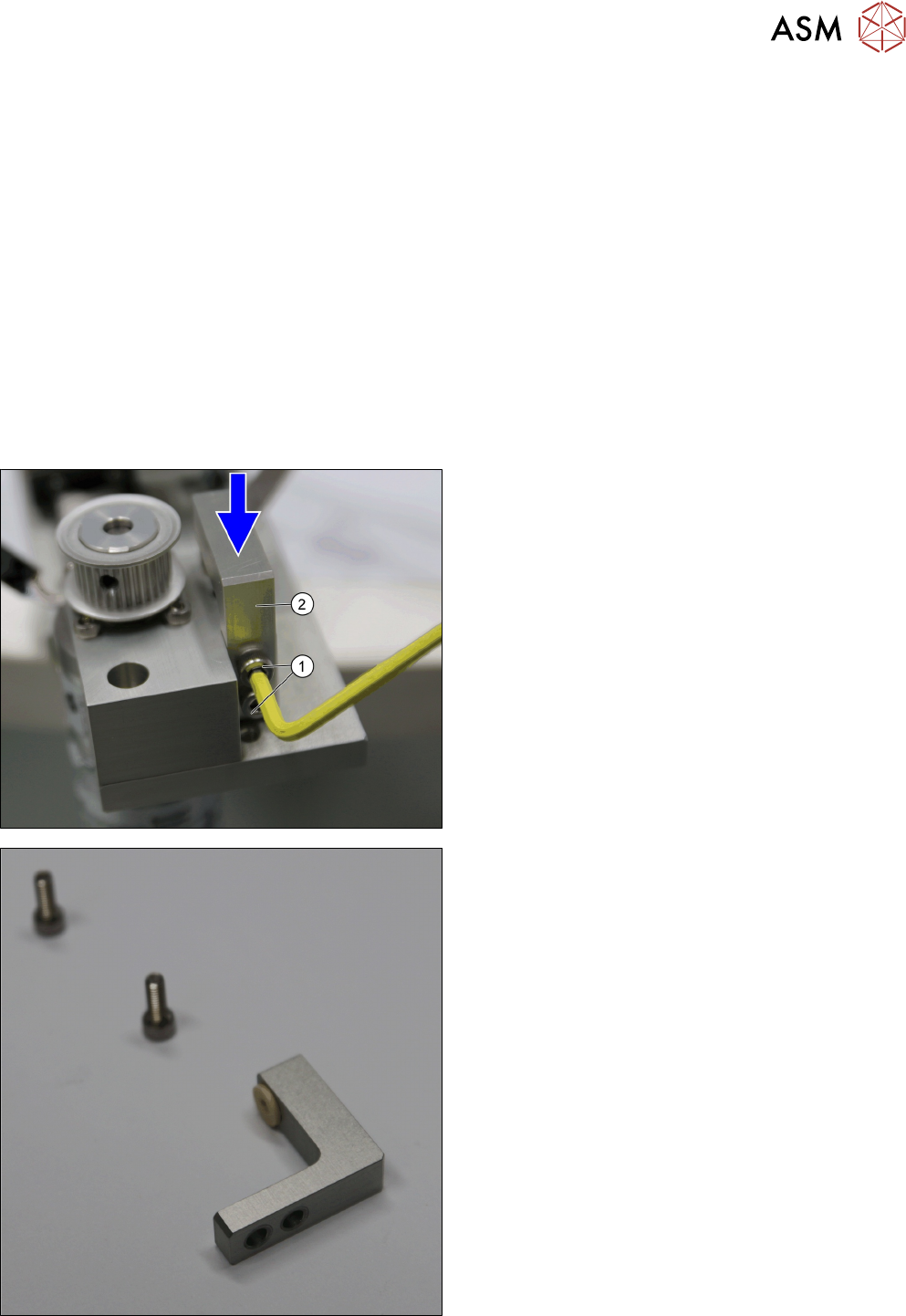
► Remove the two screws ISO 4762 - M 4 x 12-
A2-70 [03042553-xx] (1) from the Bushing Holder
top v2 [03155358-xx] (2).
► Remove the Bushing Holder top v2 [03155358-
xx] (2).
Bushing Holder top v2 [03155358-xx]