00198354-01_AI_Loc2_Fixed_Table_en.pdf - 第22页
2 Installation 2.6 Installing the E-Series Tape Cutter [03105585-xx] Assembly Instructions E by SIPLACE Location 2 Fixed Table 04/2017 22 2.6.1 Optional ► You can unfasten four M8x10, dismantle the side bracket B right […
Assembly Instructions E by SIPLACE
Location 2 Fixed Table 04/2017
2 Installation
2.6 Installing the E-Series Tape Cutter [03105585-xx]
21
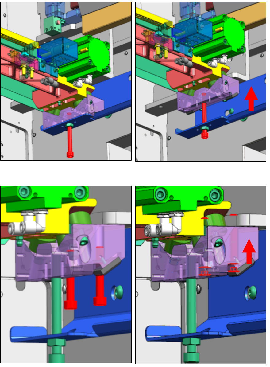
► Fasten one M10x100 screw each side (left & right) synchronously to lift up the tape cutter.
► Fasten two M8x50 cap screws each side (left and right) to the machine frame.
► Loosen M10x100 screw upon tape cutter is securely fastened.
2 Installation
2.6 Installing the E-Series Tape Cutter [03105585-xx]
Assembly Instructions E by SIPLACE
Location 2 Fixed Table 04/2017
22
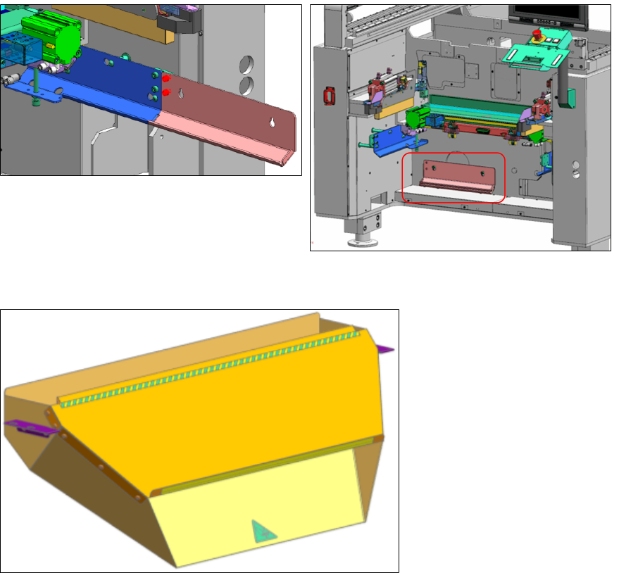
2.6.1 Optional
► You can unfasten four M8x10, dismantle the side bracket B right [03109832-xx] and side
bracket B left [03109810-xx].
► Keep and mount them onto the machine base frame.
► Install the waste tape chute [03108361-xx].
Assembly Instructions E by SIPLACE
Location 2 Fixed Table 04/2017
2 Installation
2.6 Installing the E-Series Tape Cutter [03105585-xx]
23
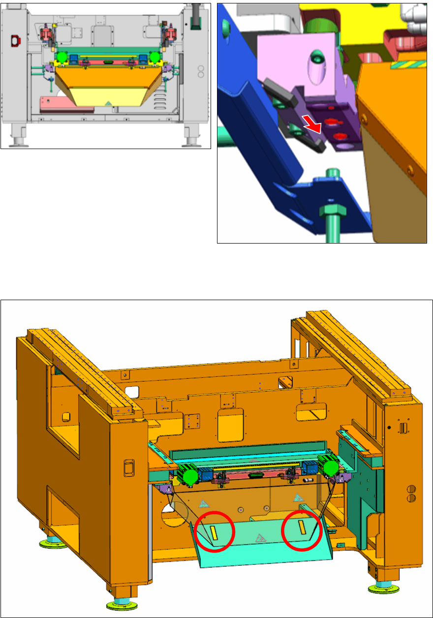
The waste tape chute has two riveted key-hole side plates.
► Mount the waste tape chute using four of M4x10 screw on to the tape cutter side holder.
► Position and paste the velcros on the locations as indicated in the drawing of [03138614-xx].
► Paste the waste tape chute extension [03136583-xx] to underside of the waste tape chute as
shown in the picture below.