RS-1XL_E.pdf - 第2页
* 4 KE-3010A □33.5 □20 0201 0603 1005 1608 AL CN SOT SOP QFN QFP Card Slot Big AL CN DI ㎜ CN Lead Long CN BGA FBGA Big QFP □50 0402 □74 0201 * 3 ∼ □74 ㎜、 50×150 ㎜ 0402 ∼ □33.5 ㎜ Conventional machine * 2 RS-1 42…
Optimum
IPC9850
*1 For metric 0201 compliance please contact us.
*2 Using RF (RF08AS) feeders.
*3 A transformer unit (option) is necessary except AC 200 V.
*4 D dimension does not include the front operation monitor. H dimension does not include signal tower.
*5 When EF feeders adapt the an attachment of EF feeder, the EF feeder can use on RF/EF feeder trolley and fixed bank (rear side). Please inquire details.
*6 Separate connection cables for each model are required.
Fast Smart Modular Mounter
Specification
RS-1XL
Board size
Component height
Component size
Placement speed
Placement accuracy
Feeder inputs
Power supply
Apparent power
Operating air pressure
Air consumption
Machine dimensions (W×D×H)*⁴
Mass (approximately)
50×50
㎜∼
650×560
㎜
25
㎜
0201 (0.250×0.125
㎜
)* ¹
∼
□74
㎜
/150×50
㎜
42,000CPH
29,000CPH
±35μ
m
(Cpk
≧
1)
Max. 112*²
AC
200
∼
415V*³ .3-phases
22 kVA
0.5±0.05 Mpa
200L / min
2,109×2,000×1,440
㎜
1,850 kg
Recognitions system
Oparations system
Inspection function
Conveyor
Electrical protection
Force Control
Software
Component handling
and feeders
Others
10 / 27/ 54 mm view camera
Rear-side operation unit / keyboard (front only)
Coplanarity sensor / Component Verification System (CVS)
Conveyor extention / Support pin / Support sponge
CE compatible specification / Ground-fault interrupter
Force control unit / Force control nozzle
JaNets / IFS-NX / Flexline CAD
Feeder Trolley (RF feeder only / RF-EF dual servo*⁵) / Electric tape feeder (RF/EF*⁵) /
EF feeder adapter*⁷ / Electric stick feeder*⁵ (Type-N / Type-W) / Matrix tray server TR8SR , TR5SNX , TR5DNX /
Matrix tray changer TR6DXLX / Dual tray server TR1RB / Tray Holder / IC collection belt /
Tape reel mounting base (for RF/ for EF) / Splicing jig / Electric Trolley Power Station PW02*⁶
Nozzle (for RS-1) / Big foot / Offset placement after solder screen-printing Solder lighting/
Non stop operation / Vacuum Pump
Option
*Please refer to the product specifications for details.
Oct - 2019/Rev.02
www.juki.co.jp
The RS-1R is an eco-friendly product which complies with JUKI
ECO PRODUCTS standards for protecting the environment.
●The machine complies with the “JUKI Group Green Procurement
Guidelines” on the use of hazardous substances, which is stricter
than other restrictions, such as those of the RoHS Directive.
For details of JUKI ECO PRODUCTS, refer to: https://www.JUKI.co.jp/eco_e/index.html
*The RoHS Directive is an EU Directive limiting the use of 6 hazardous substances(lead, hexavalent chromium, mercury,
cadmium,PBB and PBDE) in electrical and electronic equipment. The JUKI Green Procurement Guideline is the voluntarily established
criteria to eliminate not only the aforementioned six substances, but also other ones which also adversely affect the environment.
JUKI SMT ASIA CO.,LTD.
JUKI INDIA PVT. LTD.
www.smtjukiindia.com
JUKI AUTOMATION SYSTEMS INC.
www.jukiamericas.com
JUKI AUTOMATION SYSTEMS GMBH.
www.juki-smt.com
TOKYO JUKI INTERNATIONAL
TRADING (SHANGHAI) CO.,LTD.
www.jukichina.com
*
4
KE-3010A
□33.5□20
0201
0603
1005
1608
AL CN
SOT
SOP
QFN
QFP
Card Slot
Big AL CN
DI
㎜
CN
Lead Long CN
BGA
FBGA
Big QFP
□50
0402
□74
0201
*
3
∼
□74
㎜、
50×150
㎜
0402
∼
□33.5
㎜
Conventional
machine
*
2
RS-1
42,000
CPH
23,500CPH
RS-1
Case Study 1
Case Study 2
Case Study 3
【
Without RS-1
】 【
With RS-1
】
【
Without RS-1
】 【
With RS-1
】
●Component polarity is detected and corrected automatically
by the upward looking centering camera (VCS).
High-precision placement of diffusion lenses
25
㎜
1
㎜
6
㎜
12
㎜
20
㎜
3
㎜
NEW
●Upside down components
Special algorithms can detect components that are upside down
and reject them.
●Small component handling
Components down to 0201 (metric) are supported with the 10mm
field of view camera option.
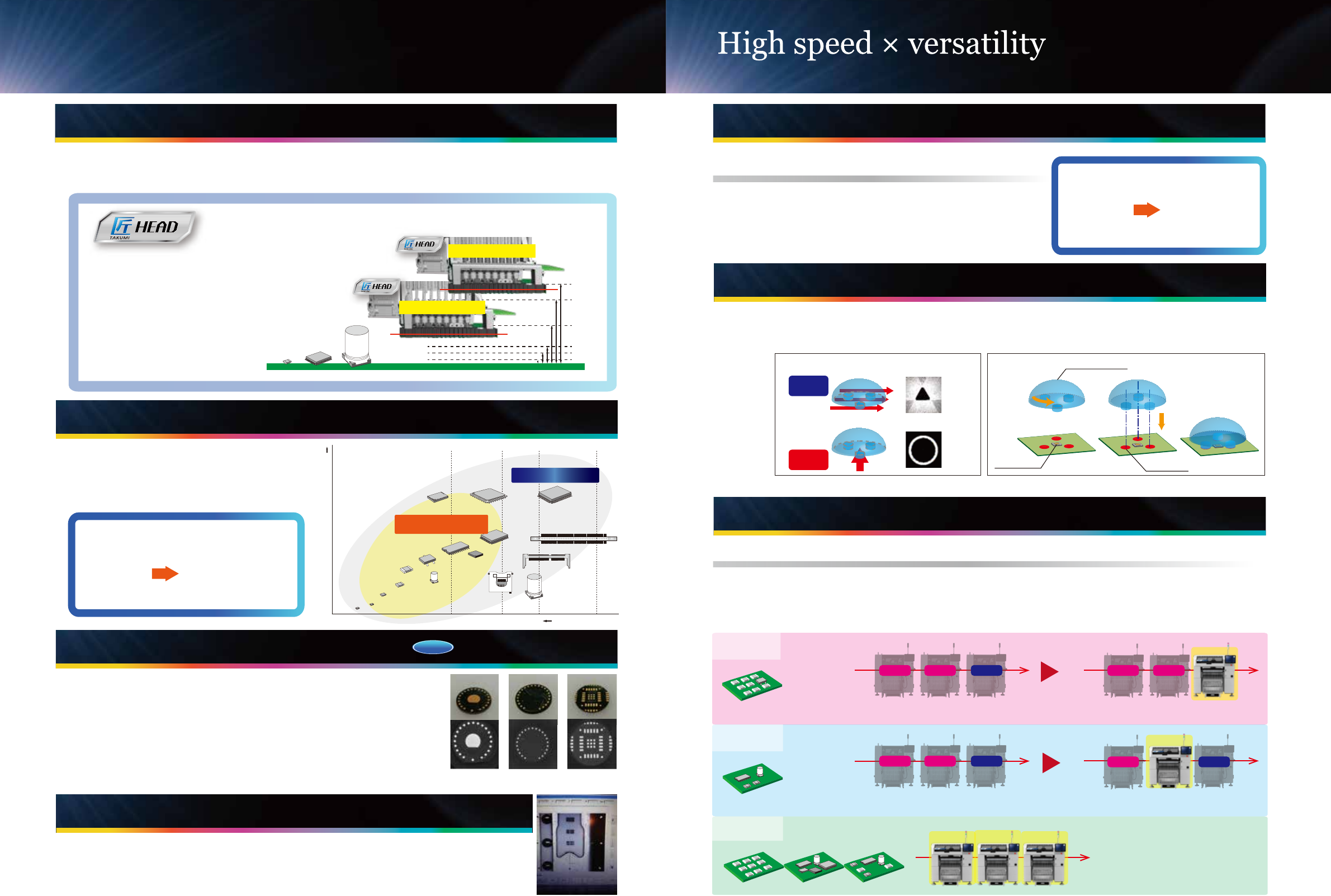
Newly developed "Takumi Head" with changing
recognition sensor height
New Dynamic Height 8 nozzle
placement head automatically adjusts
height to optimize placement speed.
This head adjusts automatically based
on the components to be placed from
1mm to 25mm in 6 different positions
(1
・
3
・
6
・
12
・
20
・
25mm).
【Variable height of the laser sensor in accordance
with the component height】
ex:component height 6mm
ex:component height 20mm
component
height
"Takumi head" that automatically optimizes it's height between 6 different positions based on component
height. Tact time is optimized by keeping the head as close to the PCB as possible for the components
placed.
PWB
Wide component range 0201 (metric) components supported
RS-1 supports components from 0201
*¹
(metric)
up to 74mm square or 50
×
150 retangular
parts. Component height up to 25mm.
*1 Please contact for details.
RS-1 component range
Component density
Advanced functionality
Conventional machine
*²
component range
【
Part correspondence power
】
*
3
Please contact for details.*
2
KE-3010A
New vision
ecognition technology
option
360-degree component recognition image
The auto tape advance funciton reduces setup time by using the fiducial camera to
advance new tapes to the first full pocket. Available for 8mm tape and components from
0402 (metric) to 3216.
Index to first full pocket
Auto tape advance function
Class leading speed, up to 42,000 cph
Class leading speed, up to 42,000 cph
Maximum speed of up to 42,000 cph*. This is made possible
by a revolutionary head design that reduces the travel time
and distance for every placement.
Conventional
machine
*1
Comparison to conventional machine
179
%
*1 KE-3010A *2 Optimum
* Optimum
【
Placement speed
*2
】
Line Balancer
Optimum line balance and highest throughput
Changing the RS-1 functionality does not require head replacement. The revolutionary design adapts to
the production requirements automatically. It can be used in-line with high speed chip placement machines
to improve overall line productivity or to make the line more flexible for complex PCBs with a high number
of large components.
JUKI laser technology realizes highly accurate placement of diffusion lens by recognizing the main orientation.
Independent control of head units Z axis achieves precise placement of large diffusion lens, avoiding
interference from other nozzles.
Centering method
○
×
Orientation determination by laser recognition Diffusion lens placement
Determination
of orientation
Laser
Vision
Diffusion lens
LED chip
Adhseive
Example PWB with
1000 chips, 50 large
components.
Products with a high percentage of small chips
results in poor utilization of flexible machines.
The flexible design for the RS-1 means it can adjust for smaller
components and maintain high speed placement capability.
Example PWB with
300 chips, 100 large
components.
Products with a high number of large components
increase the load on the flexible machine, making
it a bottleneck.
The RS-1 automatically adjusts its component capability
making it possible to balance the load across several
machines and reducing bottlenecks.
The RS-1 can change its function
dynamically from high speed chip
placement to flexible placement of large
components. This improves optimization
and line balancing for various products.
chip mounter chip mounter chip mounterchip mounter
Flexible
mounter
chip mounterchip mounter
Flexible
mounter
chip mounter
Flexible
mounter