TCM3500结构图.pdf - 第8页
MODEL TCM-3500Z-2 0109-001 6 ో࿑㧙㧝 UNIT LAYOUT -1 UNIT LA YOUT-1 Fig.2 TURNTABLE ASSEMBLY Fig.4 MIDDLE BASE ASSEMBLY Fig.3 HEAD DRIVING ASSEMBLY Fig.13 REAR COVER ASSEMBLY Fig.5 FEEDER CARRIAGE ASSEMBLY Fig.8 Fig.6 XY TA…

MODEL TCM-3500Z-2
0109-001
5
CONT-3
⋡ޓޓޓᰴ CONTENTS
Fig.11 㔚᳇ᓮㇱ ELECTRICAL SECTION
Fig.11-1 ৻ᰴ㔚Ḯ Power Supply-Primary
Fig.11-2 200V 㔚Ḯ Power Supply-200V
Fig.11-3 100V 㔚Ḯ Power Supply-100V
Fig.11-4 DC 㔚Ḯ Power Supply-DC
Fig.11-5 ࠪࠤࡦࠬࡏ࠶ࠢࠬ Relay Sequence Box
Fig.11-6 ᓮࡏ࠶ࠢࠬ Control Box
Fig.11-7 ᓮၮ᧼ࠗࠕ࠙࠻ Control P.C.B. Layout
Fig.11-8 ᓮࡏ࠶ࠢࠬ㈩✢ Control Box Wiring
Fig.11-10 ೨㕙ᠲࡄࡀ࡞ Front Operation Panel
Fig.11-11 ᓟ㕙ᠲࡄࡀ࡞ Rear Operation Panel
Fig.11-12 ᯏ᪾ᑫࠅ 1 Miscellaneous Parts-1
Fig.11-13 ᯏ᪾ᑫࠅ 2 (ࡌࠬ㕙ㇱ㧕 Miscellaneous Parts-2
Fig.11-14 ೨㕙ࠦࡦ࠰࡞ Front Console
Fig.11-15 ᓟ㕙ࠦࡦ࠰࡞ Rear Console
Fig.11-16 ೨ᓟᎿ⒟ I 㧛 F 1 Previous/Next Work Process Interface-1
Fig.11-17 ೨ᓟᎿ⒟ I 㧛 F 2 Previous/Next Work Process Interface-2
Fig.11-18 ࠦࡦࡌࠕ㚟േ࿁〝㧸 Conveyor Driver Circuit L
Fig.11-19 ࠦࡦࡌࠕ㚟േ࿁〝㧾 Conveyor Driver Circuit R
Fig.11-20 ᯏ᪾ᑫࠅ 3㧔ࡌࠬ㕙 2㧕 Miscellaneous Parts-3
Fig.11-21 ࿁↢ᛶ᛫ Regenerative Resistance
Fig.12 ࠞࡃㇱ COVER SECTION
Fig.12-1 ᚻߔࠅ Handrail
Fig.12-2 ᧄࠞࡃ Body Cover
Fig.12-3 ㇱࡈࡓ Upper Frame
Fig.12-4 ㇱࠞࡃ Upper Cover
Fig.12-5 ೨ᚺ Front Cover
Fig.13 ᓟ㕙ࠞࡃㇱ REAR COVER SECTION
Fig.13-1 ࠟ࠼ᡰᩇ Guard Stay
Fig.13-2 ᓟ㕙ࠞࡃ Rear Cover
Fig.13-3 ోࠞࡃ Guard Cover
Fig.13-4 ోࠞࡃᨒ Guard Cover Frame
MODEL TCM-3500Z-2
0109-001
6
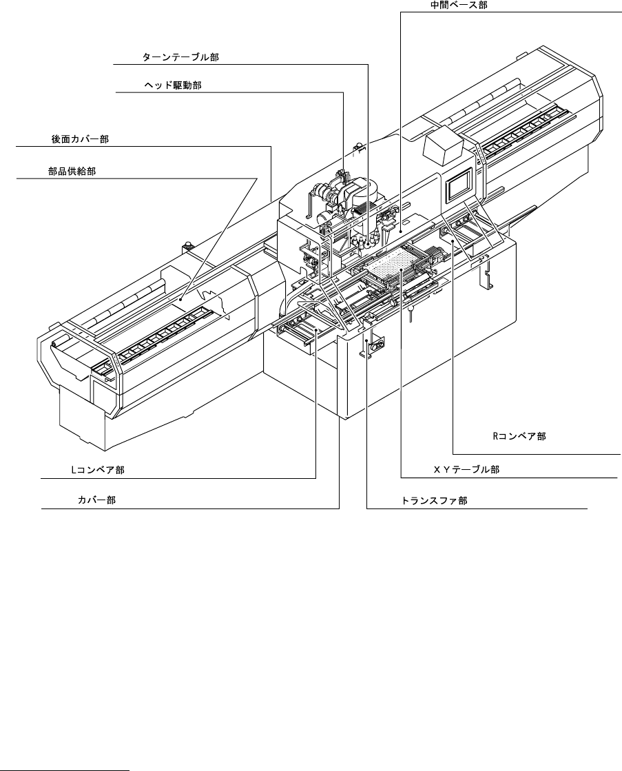
ో࿑㧙㧝 UNIT LAYOUT -1
UNIT LAYOUT-1
Fig.2 TURNTABLE ASSEMBLY
Fig.4 MIDDLE BASE ASSEMBLY
Fig.3 HEAD DRIVING ASSEMBLY
Fig.13
REAR COVER ASSEMBLY
Fig.5
FEEDER CARRIAGE ASSEMBLY
Fig.8
Fig.6 XY TABLE ASSEMBLY
Fig.9
TRANSFER ASSEMBLY
Fig.7
L CONVEYOR ASSEMBLY
Fig.12
COVER ASSEMBLY
R CONVEYOR ASSEMBLY
MODEL TCM-3500Z-2
0109-001
77
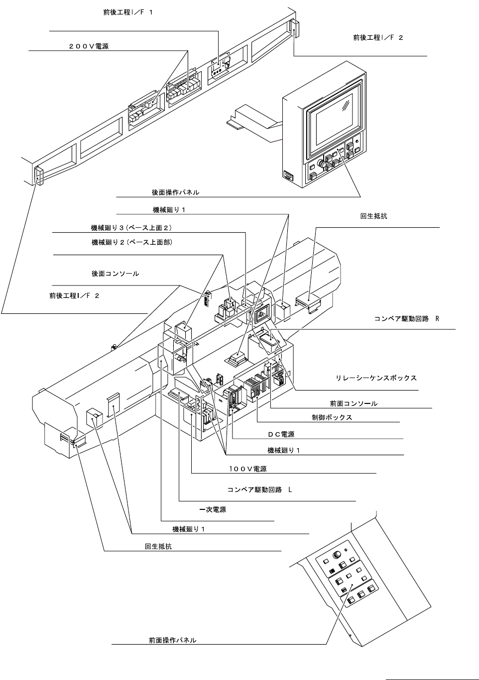
ో࿑㧙㧞 UNIT LAYOUT -2
UNIT LAYOUT-2
TCM-3500Z-2
Fig.11-16
Previous/Next Work
Process Interface-1
Fig.11-2 Power Supply-200V
Fig.11-17
Process Interface-2
Previous/Next Work
Fig.11-11 Rear Operation Panel
Fig.11-12 Miscellaneous Parts-1
Miscellaneous Parts-3Fig.11-20
Fig.11-13
Fig.11-15
Miscellaneous Parts-2
Miscellaneous Parts-1
Miscellaneous Parts-1
Rear Console
Fig.11-17
Process Interface-2
Previous/Next Work
Fig.11-19
Conveyor Driver Circuit R
Conveyor Driver Circuit L
Fig.11-5
Relay Sequence Box
Fig.11-14 Front Console
Fig.11-6~8 Control Box
Fig.11-12
Fig.11-3 Power Supply-100V
Fig.11-18
Fig.11-4 Power Supply-DC
Fig.11-1
Power Supply-Primary
Fig.11-12
Fig.11-21 Regenerative Resistance
Fig.11-21
Regenerative Resistance
Fig.11-10 Front Operation Panel