XM520.pdf - 第2页
Best speed in 1 O Spindle solution Max. 100,000 CPH lts best-in-class speed and appl,cability to wide head pitch ( 15mm) and height (H 10mm (Fly). 15mm (Stage)I extends the range of components that can be simultaneously …
THE
STANDARD
DF
FLEK/8/l/TY
XAASCCI
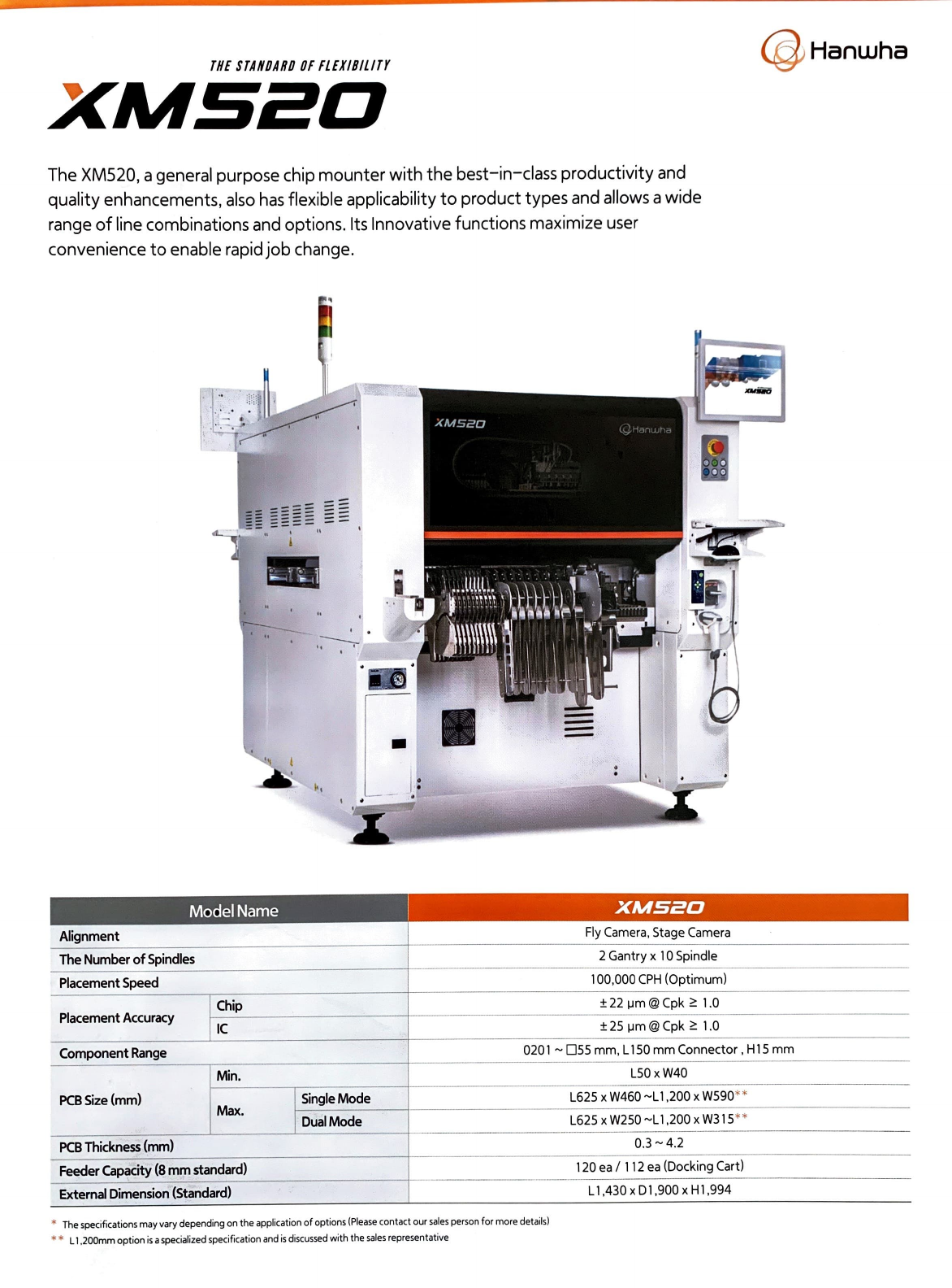
The XM520, a general purpose chip
mounter
with
the
best-in-class productivity and
quality enhancements,
also
has
flexible applicability
to
product types and allows a wide
range
of
line combinations and options. lts lnnovative functions maximize user
convenience
to
enable rapidjob change.
-
,
..
ModelName
Alignment
The
Number
of
Spindles
Placement
Speed
Placement
Accuracy
Chip
IC
.
.
.
.
• 1
'
1
XMSif!O
Fly
Camera,
Stage
Camera
2 Gantry x 1 O Spindle
100
,000
CPH
(Optimum)
±
22
µm@
Cpk
1.0
±25 µm@Cpk
1.0
@ Hanwha
Component
Range
0201
~
055
mm, L
150
mm Connector, H
15
mm
Min.
L50
x
W40
PCB
Size
(mm)
1
Single
Mode
L625
x
W460
~L 1,
200
x
W590
* *
Max.
1
DualMode
L625
x
W250
~L
1,200
x
W315
**
PCB
Thickness
(mm)
0
.3
~4.2
Feeder
Capacity
(8
mm
standard)
120
ea/
112
ea
(Docking
Cart)
Externa!
Dimension
(Standard)
Ll,430 x
D1
,900
x Hl ,994
*
The
specifications
may
va
ry
depending
on
the application of options
(Please
contact
our
sales
person
for
more
details)
* * L 1,200mm option
is
a specialized specification
and
is
di
scussed
with
the
sales
representative
Best
speed in 1 O Spindle solution
Max.
100,000
CPH
lts best-in-class
speed
and
appl,cability to
wide
head
pitch (
15mm)
and
height
(H
10mm
(Fly).
15mm
(Stage)I
extends the
range
of
components that
can
be
simultaneously picked
up,
achieving
high
actual
productivity for
components from microchips to odd-shape
components.
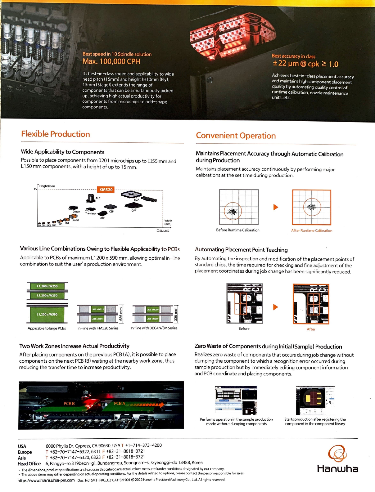
Flexible
Production
Wide
Applicability
to
Components
Possible
to
place
components
from
0201 microchips
up
to
mm
and
L 150
mm
components
,
with
a
height
of
up
to
15
mm.
Height (
mm
)
15
----
-----
- -
--
- - - -
---
-
--
.-
----
~
--
~
----------:
..
Oiocle
..,.
l!!D
lllfi'i
Ta nta l
:1:
s
:2
= \
OOS
l&ll
ALC
B
GA----
:
---
~ :
~
CSP
QFP
:
Tr
ar\51Stor
.........
:
SOP 1
:
Wid
th
: (m m)
O
55,
Ll
S0
Various
Line
Combinations
Owing
to
Flexible
Applicability
to
PCBs
Applicable
to
PCBs
of
maximum
L 1200 x 590
mm
, allowing
optim
al
in-
lir
,e
combination
to
suit
the
user' s
production
environment
.
=~
L1,2ooxw2s
_o "
L
1,200
x
W250
·'
'\
l1,200xWS90
Appl
icable
to
large
PCBs
ln
- line
with
HM520 Seri
es
ln-line with
DECAN
/
SM
Ser
ies
Two
Work
Zones
lncrease
Actual
Productivity
After
placing
components
on
the
previous
PCB
(A),
it
is
possible
to
place
components
on
the
next
PCB
(B)
waiting
at
the
nearby
work
zone, thus
reducing
the
transfer
time
to
increase
productivity
.
USA
6000
Phyllis
Dr
.
Cypress
,
CA
90630
,
USA
T + 1-714- 373-4200
Europe
T +82-70-7147-6322,6311 F +82-31-8018-3721
Asia
T +82-70-7147-6320,
6323
F +82-31-8018-3721
Best
accuracy
in
class
±
22
µ m @
cpk
1.0
Achieves
best-in-class placement
accuracy
and
mainta,ns
high
componen! placement
quality by automating quality control
of
runtime calibration. nozzle maintenance
units. etc.
Convenient Operation
Maintains
Placement
Accuracy
through
Automatic
Calibration
during
Production
Maintains placement accuracy
continuou
sly
by
per
forming
major
calibrations
at
the
set
time
during
production
.
_L
l.
-¡-¡--
Before Runtime
Ca
li
brat ion
After
Runtime Calíbration
Aut
omating
Placement
Point
Teaching
By
a
utomating
the
inspection and
modification
of
the
placement points
of
stan dard chips ,
the
time
required
for
checking and fine adjustment
of
t he
pla
cement
coordinates during
job
change
has
been significantly reduced.
Before
After
Zero
Waste
of
Components
during
lnitial
{Sample)
Production
Realizes zero waste
of
components
that
occurs
duringjob
change
without
dumping
the
component
to
which a recognition error occurred
dur
ing
sample
production
but
by
immediately
editing
component
information
and
PCB
coordinate and placing components.
Performs op
era
tion in t he
sa
mp
le production
mode wi
th
o
ut
dump
ing
co
mponent s
St a
rt
s production
after
re
gi
stering the
co
mponent
in the component library
Head
Office
6, Pangyo-ro 3 19beon-gil, Bundang-gu,
Seongnam-si,
Gyeonggi-do
13488,
Korea
@
Hanwha
• T
he
dimensio n
s.
pr
od
u
ct
sp ecificatío ns and v
al
u
es
in t hi s catal
ogar
e actu
al
values m_easured under c~nd1tions designa
ted
by
ou
r company .
• Th e
above
items
m ay d
iff
er
depe
nd
ing en a
ct
ual operat1
ng
condit ions.
Fe
r t he
de
t a
1l
s related
to
opt
1ons, please
contact
the person responsible
for
sales.
https://www.hanwha-pm.com Doc. No: S
MT
-PK
G_02-CAT
-E
N-00 1 © 202 2
Ha
n
wha
Precisio n Machinery Co., Ltd. A
II
rights reserved