yg200_mpl_je.pdf - 第4页
Contents 7 Operation Panel Section Operation Panel.................................................... 7-1 8 Conveyor Unit Section Push Up ................................................................ 8-1 PCB Stopper …
Note
Rank A : The functions of these parts gradually deteriorate with operating time.
Rank B : The machine stops immediately if the functions of these parts are disabled.
Rank C : The machine still operates even if the functions of these parts are disabled,
because there are many parts.
Rank E : The functions of consumable part gradually deteriorate with operating time.
/ : Maintenance is excluded (The screws are also equal, display is omitted)
Level
: Aims to undergo basic maintenance training and have the capability to do the
job.
Level
r
: Yamaha Corp. aims to render exclusive training
Level
Í
: Yamaha Corp. Service Engineering
Rev.
: It had a change without the compatibility. Please be careful at the time of the
parts ordering.
Level column
Make use of these as reference, “
•
r
•×”, as mentioned in the Level column.
“
” It is based on taking the basic maintenance training, and being able to do
equal work.
“
” Please contact our company service when it is judged that the customer’s
condition difcult.
From the problem that arises from these, we cannot assume responsibility such as
accidents.
NOTE
RankA: 機能が徐々に失われる可能性のある部品。
RankB: 機能を失うとマシンの即停止に繋がる部品。
RankC: 機能を失っても複数あるのでマシンの即停止とはならない部品。
RankE: 機能が徐々に失われていく消耗部品。
/ :メンテナンス対象外(ネジ類も同等、但し表示省略)
Level
: 基礎メンテナンストレーニングを受けた方、又は同等の作業ができる方が対象。
Level
r
:ヤマハの専用トレーニングを受けた方が対象です。
Level
Í
: ヤマハのサービスマンが対象です。
Rev.
:過去に互換性の無い変更が入った部品。部品発注時は注意してください。
Level 欄について
Level 欄に記載されている
“
•
r
•×”
はご参考としてご活用ください。
“
”
は基礎メンテナンストレーニングを受けた方、又は同等の作業ができる方を
基準にしております。
“
”
であってもお客様が難しいとご判断された時は弊社サービスまでご連絡ください。
これらに起因する不具合、事故等についての責任は負いかねます。

Contents
7
Operation Panel Section
Operation Panel....................................................7-1
8
Conveyor Unit Section
Push Up ................................................................8-1
PCB Stopper .........................................................8-2
Side Clamp Pos. Assy ..........................................8-3
Fixed Conveyor Ent. / Exit (R) ..............................8-4
Moving Conveyor (R) ............................................8-5
9
Blow Station Section
Blow Station ..........................................................9-1
Filter Assy .............................................................9-2
10
Controller Section
Control Box .........................................................10-1
11
Exterior, etc. Section
Exterior, etc. ........................................................11-1
Key Board & Mouse............................................11-2
12
Tools Section
Tools ...................................................................12-1
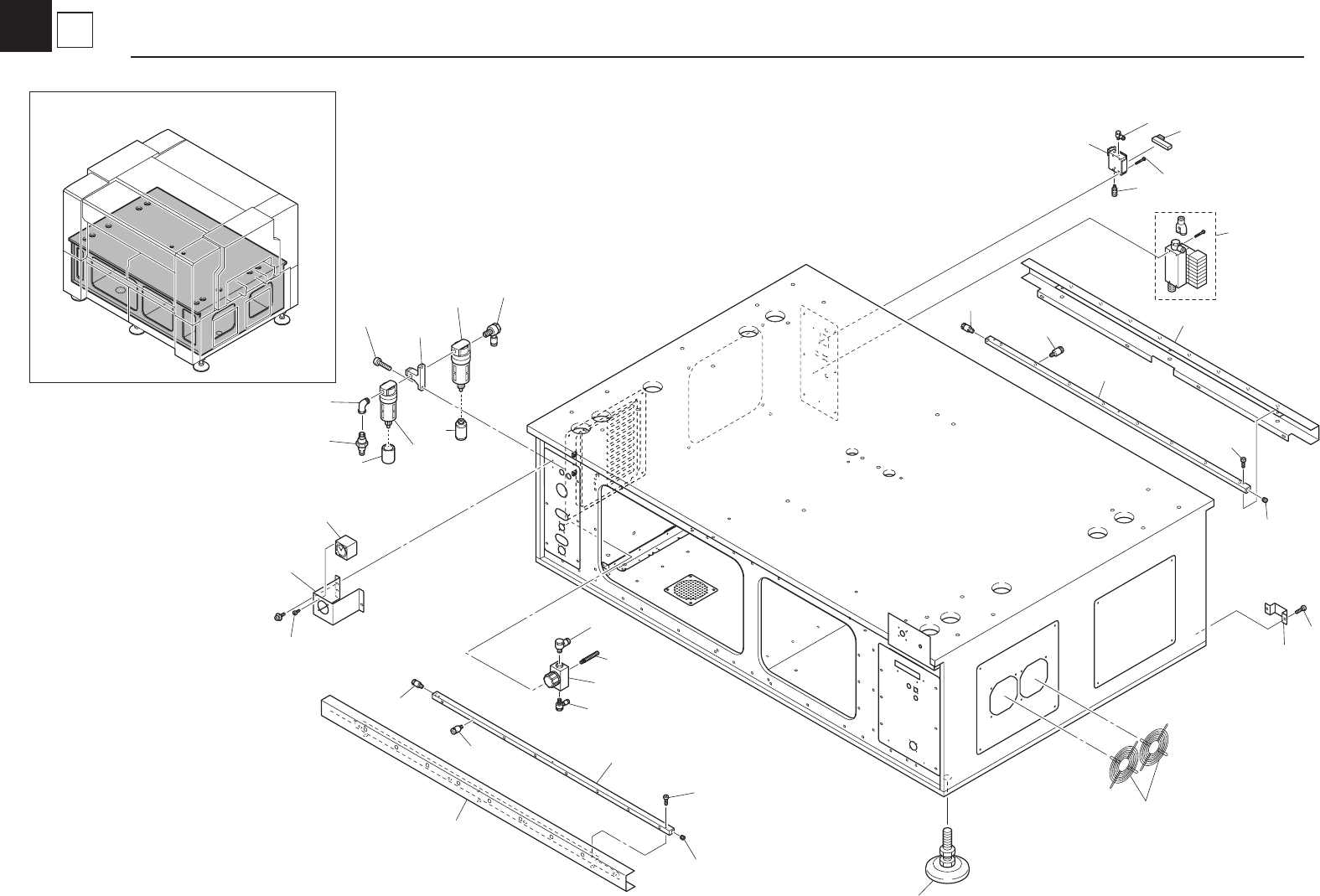
1 Base Section
Base .....................................................................1-1
2 Cover Section
Top Cover .............................................................2-1
Base Cover ...........................................................2-2
3
Moving-axis Section
X-axis ....................................................................3-1
Y-axis ....................................................................3-2
YT-axis ..................................................................3-3
4
Feeder Holder Section
Feeder Holder 20 / FES 20Carriage / FES 20 Clamp Unit
.....4-1
Feeder Floating Detection 20 (Before February 2006)
.....4-2
Feeder Floating Det. -Op-(Before April 2009) ......4-3
Feeder Floating Det. -Op-(After May 2009) ..........4-4
5
Head Section
Normal Head ........................................................5-1
FNC Head. ............................................................5-2
Head Combination. ...............................................5-3
6
Nozzle Section
Nozzle Selection ...................................................6-1
15
16
21
21
2
3
4
27
23
1
5
5
6
7
8
9
28
7
8
9
28
21
14
13
12
31
18
17
24
6
20
30
11
22
10
29
25
26
KGT-081105
1
1
Base
Base