00192299-02.pdf - 第106页
2 Retrofitting Instructions: Mechanical Ceramic Substrate Centering HS -50 SIPLACE HS -50 2.7 Checking the Function 01/01 Issue 106 ( UURU0HV VDJHV 3RVVL EOH& DXVHV If an error occurs, t he foll owing erro …
SIPLACE HS-50 2 Retrofitting Instructions: Mechanical Ceramic Substrate Centering HS-50
01/01 Issue 2.7 Checking the Function
105
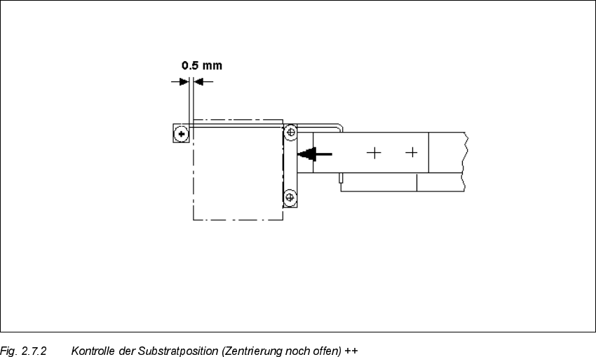
Å In processing area 1 loosen the screws fastening the connection rail on inside left and inside
right of the conveyor assemblies (2 socket hex head cap screws M 4 each).
Å Move the connection rails (incl. guide rods and stopper) the required diistance in PARALLEL
in the direction of the ceramic substrate centering unit and retighten the screws to fasten the
connection rails in this position.
Å Conduct a trial placement with substrate and check whether the fiducials of the substrate can
be reliably recognized. If necessary, select a different type of illumination (see User Manual).
2 Retrofitting Instructions: Mechanical Ceramic Substrate Centering HS-50 SIPLACE HS-50
2.7 Checking the Function 01/01 Issue
106
(UURU0HVVDJHV3RVVLEOH&DXVHV
If an error occurs, the following error message is output:
– "Error ceramic substrate centering
"
or
– "Error ceramic substrate centering
"
This stops the placement sequence.
The message means that the proximity switch signal for "opened" (1) / "closed" (0) is not present.
– The suffix
means: The error is in processing area 1 or 4 (see Fig. 2.1.1).
– The suffix
means: The error is in processing area 2 or 3 (see Fig. 2.1.1).
3RVVLEOH&DX VHV
– Problem in compressed air branch / leaky connection / poor, missing or incorrectly allocated
plug-in connection of the solenoid valve cable on the solenoid valve / faulty solenoid valve.
– Incorrect triggering distance / tension spring on the flat cylinder unhooked, poor, missing or in-
correctly allocated plug-in connection of the proximity switch cable on the X-centering unit /
faulty proximity switch.
– Incorrectly allocated plug-in connection on the conversion board (X34/X35) or plug-in connec-
tions for conveyor 1 and 2 switched.

SIPLACE HS-50 2 Retrofitting Instructions: Mechanical Ceramic Substrate Centering HS-50
01/01 Issue 2.8 Reinstallation to PCB Clamp
107
5HLQVWDOODWLRQWR3&%&ODP S
7RROV$X[LOLDU\0DWHULDOVDQG(TXLSPHQW
–Allen wrench 3
– Oblique-nosed cutting pliers
NOTE:
The following steps are required for reinstallation:
- Mount holddown bracket on the existing holddown for the substrate centering.
- Deinstall the mechanical ceramic substrate centering unit from the lifting table.
- Put proximity switch cable and pneumatic hose into the cable pit.
- Undo all plug-in connections of the mech. substrate centering unit on the conveyor control.
The reinstallation must always be carried out in BOTH processing areas of the conveyor in ques-
tion.
Å Turn the machine OFF and isolate the machine from the mains (see DANGER text in the Sec-
tion 2.2).
Å Mount the PCB holddown bracket (see Fig. 2.5.3 -> 14, 15) from the retrofit kit of the ceramic
substrate centering unit on the existing holddowns (6 cross-slotted screws M3 for each).
Å CAREFULLY undo the cable ties used to fasten the proximity switch cable and the pneumatic
hose next to the centering unit (see Fig. 2.5.14) and on the rail of the conveyor width adjust-
ment assy (see Fig. 2.5.15).
Å Undo the plug-in connection of the proximity switch cable and the thread hose coupling of the
pneumatic connection on the pertinent centering unit (see Fig. 2.5.4).
Å 'HLQVWDOOWKHPHFKDQLFDOFHUDPLFVXEVWUDWHFHQWHULQJXQLWIURPWKHOLIWLQJWDEOH
(see Fig. 2.5.4). To do this, proceed in the reverse order to that describe for installation in
Section 2.5.7.
Å Open the pertinent cable pits (see Overview, Fig. 2.5.7).
Å Stow the pneumatic hoses and proximity switch cables in the pertinent cable pit.
Å 8QGRWKHSOXJLQFRQQHFWLRQVRIWKHRSWLRQRQWKHFRQYH\RUFRQWURO
– In the case of series handling TSP 200:
On the conversion board of the conveyor control in the PCB conveyor area (see Fig. 2.9.5).
– Or in the case of changeover handling TSP 200:
On the "piggyback board" (conversion board) of the der conveyor control in the machine
frame (see Fig. 2.5.13). For the deinstallation / reinstallation of the side panel on the ma-
chine frame, proceed as described in Section 2.5.11.