Machine Overview.pdf - 第18页
MACHINE OVERVIEW MACHINE PRINT CYCLE 4.18 Technical Reference Manu al Chapter Issue 4 Nov 09 22. The rising table is lowered to sep arati on dist ance at separation speed. Once separation dist ance has been reached the r…

MACHINE OVERVIEW
MACHINE PRINT CYCLE
Chapter Issue 4 Nov 09 Technical Reference Manual 4.17
MACHINE PRINT CYCLE
The following is a typical machine print cycle with camera mounted board stop:
1. Run is selected, the printhead cover lock is engaged and the rising table
carries out a rail lifted check.
2. The camera positions itself at the board stop co-ordinates.
3. The print carriage moves to the start of the print stroke and both squeegees
drive to their set dwell height. The chase clamps are applied clamping the
chase in position.
4. The board is transported into the machine stopping at the board stop.
5. The transport belts stop running as soon as the board stop sensor detects
the board.
6. The board clamp mechanism operates, clamping the board in position and
the board stop retracts.
7. The camera carriage drives to the position determined by Fiducial 1 X & Y
co-ordinates.
8. The print carriage is driven to its enhanced start position and the appropriate
squeegee is driven down to start height.
9. The rising table carries out a rail lift check and drives up to vision height.
10. The vision data window displays the board fiducial on the left and the stencil
fiducial on the right of the split display.
11. The fiducials are located and a small blue cross with the fiducial outline
appears in the centre of each fiducial on the split display indicating success-
ful location.
12. While the camera drives to Fiducial 2 X and Y coordinates, the location of
the Fiducial 1 board and stencil fiducials are copied to the align data
structure.
13. Fiducial 2 board and stencil fiducials are located.
14. The chase clamps are de-energised and the screen actuators carry out a
rough alignment on the screen. The chase clamps are re-applied securing
the screen.
15. The camera relocates Fiducial 1 and 2. On completion, the camera carriage
drives to its home position.
16. The chase clamps are de-energised and fine alignment on the screen is
carried out. On completion, the chase clamps are re-applied.
17. The relevant squeegee is driven down to make contact with the screen with
0.5kg force.
18. The rising table drives up to the print height.
19. The appropriate squeegee is driven down to the calculated pressure setting,
as set in the board parameter menu.
20. The print carriage drives in the appropriate direction to perform a print
stroke.
21. The squeegee mechanism releases full pressure but keeps the squeegee
in contact with the stencil with 0.5kg force (hold height).

MACHINE OVERVIEW
MACHINE PRINT CYCLE
4.18 Technical Reference Manual Chapter Issue 4 Nov 09
22. The rising table is lowered to separation distance at separation speed. Once
separation distance has been reached the rising table accelerates to its
normal speed, lowering the table to transport height. The board clamps are
released and the relevant squeegee is raised to dwell height.
23. The front and rear transport belts drive until the board is detected at the
output sensor and the chase clamps are released.
24. The board count, paste dispense and screen cleaner cycle counts are
incremented. If either the paste dispense or screen cleaner counts has
reached the values set by the dispense rate or clean screen rate, the
appropriate cycle is performed.
MACHINE OVERVIEW
ELECTRICAL SCHEMATIC
Chapter Issue 4 Nov 09 Technical Reference Manual 4.19
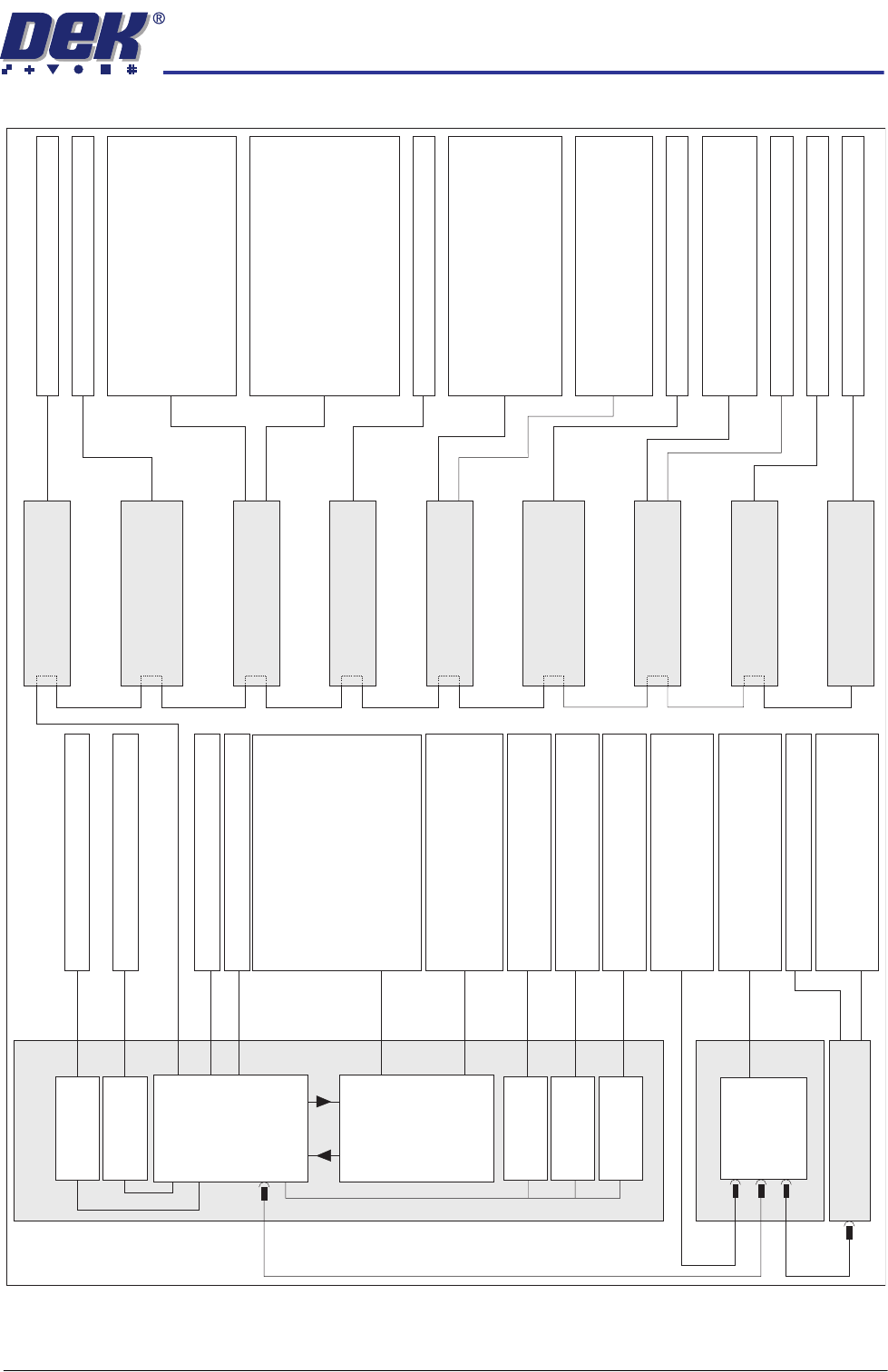
ELECTRICAL SCHEMATIC
X Forward Actuator
X Rear Actuator
USB
USB
USB
PC
Motherboard
M36 Machine
Control Enclosure
NextMove
Interface
Dual Stepper
Card X3
Dual Stepper
Card X2
Dual Stepper
Card X1
NextMove ES
(I/O Node 1)
I/Ps O/Ps
CAN Bus
O/Ps
O/Ps
I/Os
Front Squeegee Motor
Rear Squeegee/ProFlow Motor
Y Actuator
Moving Rail Motor
M37 Power
Supply Module
O/P
I/Ps
O/Ps
Camera Trigger
Transport Belt Motors
FMI
E Stop Power
I/Ps
Squeegee Home Sensors
Transport Rail Sensors
Board Stop Sensors
Jog Buttons (via M37)
Cover Interlock
FMI
Power ‘ON’ Monitor
Camera X Home (Linear Motor)
Camera Y Home (Linear Motor)
System Switch
Jog Buttons
E Stop
MMI Touchscreen
IR Keyboard/Mouse
USB Flash Drive
Host Comms
DEK Interactiv
Camera S
ystem (vision)
Aout
Temperature to ECM
Ain
O/Ps
USC Solvent Level
System Lamp
Chase/Screen/Board Clamps
Lid Bolt
USC Cleaner Squeegee
Board Stop
Tricolour Beacon
Vacuum Tooling Power
Air Pressure Sensor
Lid Bolt Sensor
Vacuum Tooling Sensor
Screen Sensor
Camera Y Home (Rotary Motor)
Print Carriage Home Sensor
Pass Through Rails Home Sensor
Paste Carriage Home Sensor
Servo Node 8
(Camera X Rotary Motor)
I/P
Camera X Home (Rotary Motor)
Rising Table Home Sensor
USC Sensors
USC Home Clamps
Solvent PumpUSC Motors and
Vacuum Power
Drip Tray Solenoid
Paste Cartridge Tilt Solenoid
Paste Dispense Solenoid
Screen Actuator
Paste Height Laser
ProFlow Paste Pressure
ProFlow SCAR
Drip Tray Sensor
Paste Cartridge Horizontal/Vertical
Paste Level Sensor
ProFlow Link - ProFlow SCAR
Screen C
ylinder Sensors
Paste Roll Low
Screen Position Sensor
Squeegee Pressure
I/Ps
Servo Node 6
(Rising Table Motor)
I/P
Stepper Node 10
(Paste Dispense
Stepper Motor)
O/Ps
I/Ps
I/O Node 3 Board
(Print Carriage)
I/P
Servo Node 7
(Print Carriage Motor)
O/Ps
I/Ps
I/O Node 2 Board
(Main Machine)
Stepper Node 15
(Pass Through Lane
Rail Width Motor)
I/P
I/P
Servo Node 9
(Camera Y Rotary Motor)
O/Ps
I/Ps
I/O Node 4 Board
(Screen Cleaner)
EuroFlex
Card X7
EuroFlex
Card X6
Camera X MotorLinear
Camera Y MotorLinear