200823.TR3000-IRV English Manual.pdf - 第2页
IR AUT O BGA R ework S tation TR3000-IRV Kukjetrading Co., Ltd. 2 Table of Contents 1 <Caution> ... ... ... ... ... ... .... ... ... ... ... ... ... ... .... ... .. ..... .. ... ... ... .... .. ... .... ... ... ...…

IR AUTO BGA Rework Station TR3000-IRV
Kukjetrading Co., Ltd.
1
IR AUTO
BGA Rework Station
User Manual
TR3000-IRV
Full HD
<H/W Ver: 2.2 HMI Ver: 1.1>
Kukjetrading Co., Ltd.
Jungang-ro 220, Yangcheon-gu, Seoul (Sinjung-dong 3rd Floor)
TEL: +82-2-2648-4644
FAX: +82-2-2648-4601
E-mail: kukjetrad@kukjetrad.co.kr
Homepage: http://www.kukjetrad.co.kr

IR AUTO BGA Rework Station TR3000-IRV
Kukjetrading Co., Ltd.
2
Table of Contents
1 <Caution> ................................................................................................................................................................. 3
2 <Warning> ................................................................................................................................................................ 4
3 Features and Specifications .................................................................................................................................... 5
3.1 Features ..................................................................................................................................................... 5
3.2 Specifications ............................................................................................................................................. 6
3.2.1 Size ............................................................................................................................................ 6
3.2.2 Electric Features .................................................................................................................... 6
3.2.3 Structure .................................................................................................................................. 6
4 Installation ................................................................................................................................................................ 7
5 Start ........................................................................................................................................................................ 10
6 BGA Rework Station Parts .................................................................................................................................. 12
7 Controller Screen .................................................................................................................................................. 14
7.1 OPTION(Initial Setting) ............................................................................................................................ 17
7.2 About DATA .............................................................................................................................................. 19
7.2.1 Use DATA ............................................................................................................................. 20
7.3 About FILE................................................................................................................................................ 22
7.3.1 Registration of New Temperature Profile ........................................................................... 23
7.3.2 Switch Over of Temperature Profile ................................................................................... 25
7.3.3 About Operation Mode ........................................................................................................ 25
8 Operation of Device .............................................................................................................................................. 27
6.1 How to Remove Parts .............................................................................................................................. 27
6.2 Removal of Soldering Residual on PCB (USE A BOTTOM HEATER) .................................................. 27
6.3 How to Soldering ..................................................................................................................................... 27
6.3.1 SOLDERING after Dipping .................................................................................................. 27
6.3.2 SOLDERING without Dipping ............................................................................................ 28
6.3.3 SOLDERING with No Use of Vision Function .................................................................... 28
6.3.4 Reheating ................................................................................................................................ 28
6.4 MOUNT(Mounting Test) .......................................................................................................................... 28
6.5 Vision Calibration ................................................................................................................................... 29
9 Safety Device ........................................................................................................................................................... 32
<Appendix 1> List of Service Supplies ................................................................................................................... 34
<Appendix 2> Temperature Profile input data ..................................................................................................... 35
IR AUTO BGA Rework Station TR3000-IRV
Kukjetrading Co., Ltd.
3
<Caution>
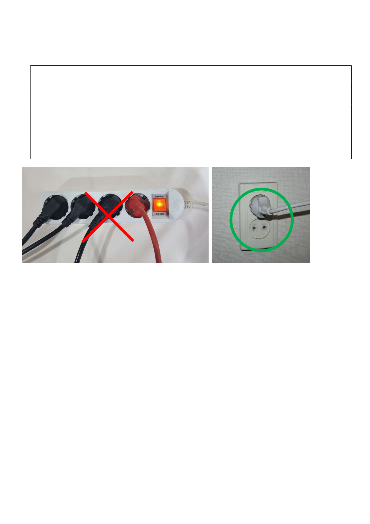
1. The supply power voltage for this device must be AC220V, 50/60Hz, 16A. The device could malfunction or a
circuit breaker cuts the power when it is plug in a multitap. Please use the proper power supply. The macine must
be connected to ground.
2. The device can get extremely hot while it is on and after use. Please be aware of burns.
3. When the PCB is heated, harmful gases could be arisen. Therefore, a ventilation duct must be installed before use.
4. Do not leave the device unattended or do not execute the heating operation while the vacuum is on. A vacuum
pump or pipe could be damaged.
5. Please determine the installation direction upon installation of the PCB onto a table. There should be no obstacles
in an area subject to the sensor detection. If there is any reflector or tall component, it may interrupt the detection
of a sensor which consequently leads to interruption of the device control.
6. Do not adjust the direction for an infrared ray sensor. If the direction is adjusted, the control temperature would be
changed so the temperature calibration would be required additionally.