P-0299-004.pdf - 第21页
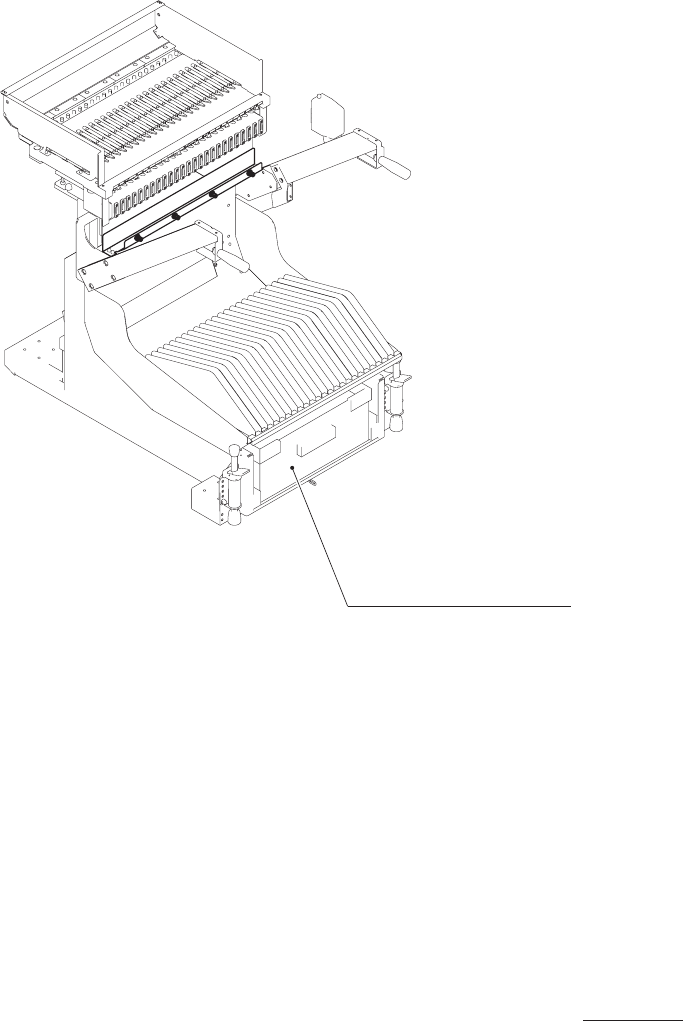
G -S161-03 0801-002 注) イラストはフィーダカートにフラックス塗布ユニットを装着した場合の、 エア分岐配管追加箇所を示しております。 Notice ) The illustration shows the air additional branch line(s) when the flux dispensing unit is mounted onto the feeder cart. フィーダカート部 Fig.B…

MEMO
G -S161-03
0801-002
17
16
68
51
68
51
14
14
15
17
41
42
22
21
31
31
72
38
33
33
18
34
1
52
.
54
.
53
52
.
54
.
53
64
.
63
.
62
55
.
57
.
56
55
.
57
.
56
60
.
63
60
.
63
59
.
57
.
72
61
.
63
.
62
61
.
63
.
62
58
.
57
.
72
69
69
55
.
57
.
56
64
.
63
.
62
48
47
46
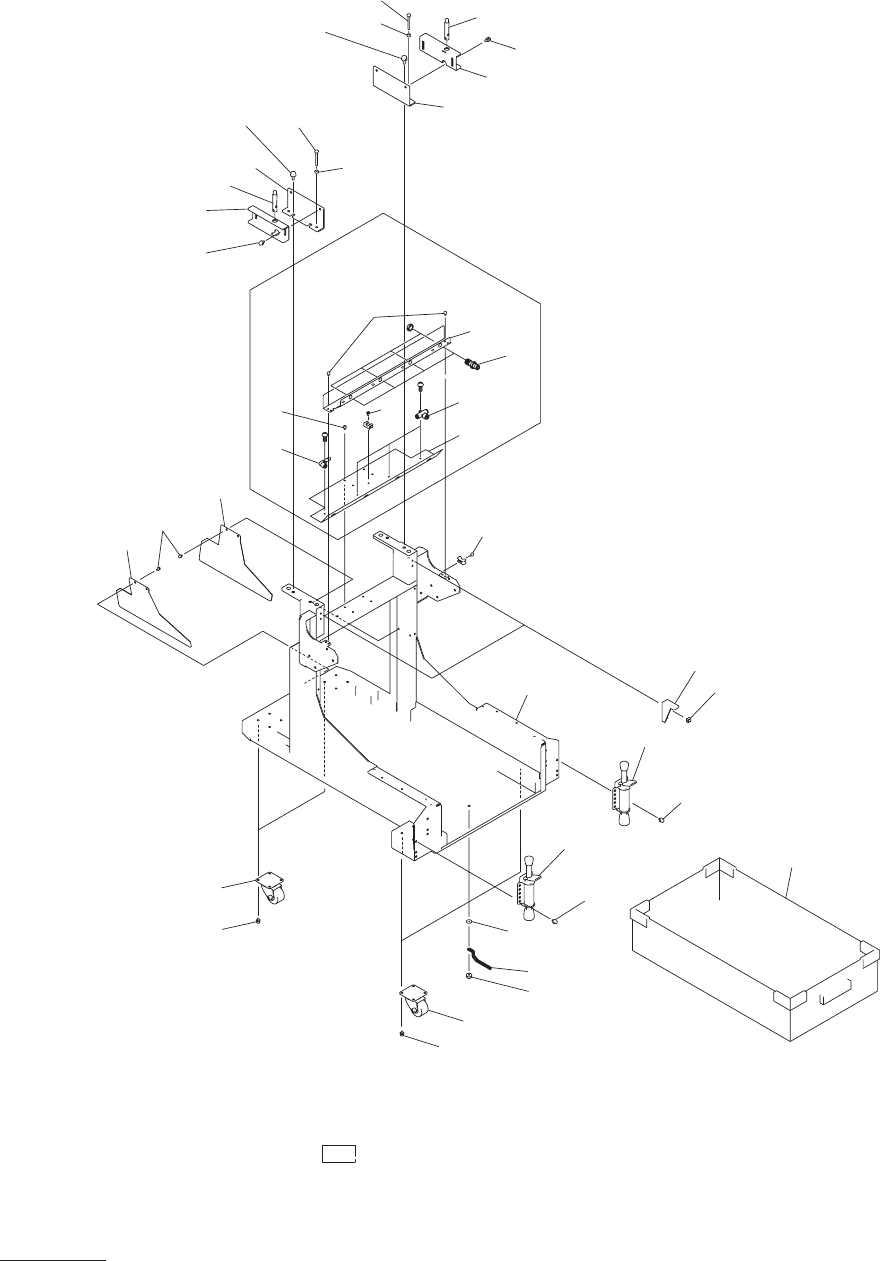
内がエア分岐配管追加箇所です。
The explanation in brackets is for the locations to the air additional branch line(s).
フィーダカート部
FEEDER CAR
T SECTION
Fig. B-1
フレーム部
Frame Section
B-1 illust-1