Infinity EX Printhead Lift.pdf - 第2页
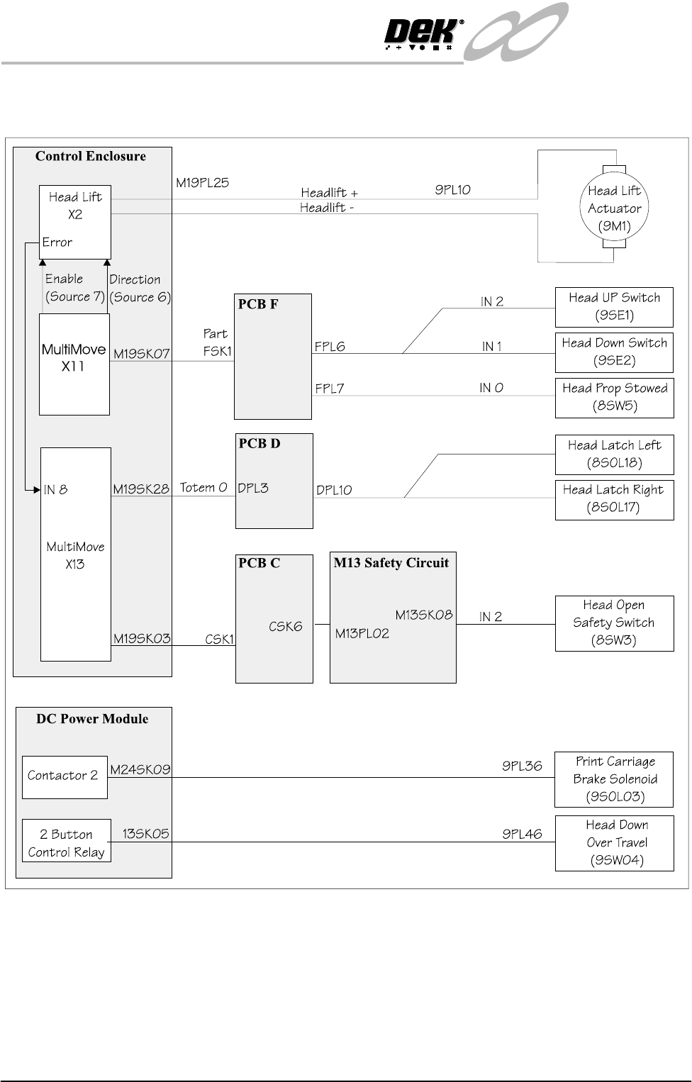
INFINITY EX PRINTHEA D LIFT MODU LE PRINTHEA D SCHE MATIC 8.2 Technical Reference Manu al Chapter Issu e 2 Jan 04 PRINTHEAD SCHEMA TIC

INFINITY
EX
PRINTHEAD LIFT MODULE
MODULE OVERVIEW
Chapter Issue 2 Jan 04 Technical Reference Manual 8.1
CHAPTER 8 PRINTHEAD LIFT MODULE
MODULE OVERVIEW
Purpose The printhead lift module raises and lowers the printhead of the machine to allow
access to the following modules:
• Camera and Vision Module
• Board Support Tooling Module
• Underscreen Cleaner
•Rail System
The components mounted on the printhead that are lifted with it are:
• Print Carriage Module
• Squeegee or ProFlow Module
• Paste Dispense Module
• Screen Change Module
• Screen Alignment Module
• Printhead Covers and Front Bezel
Elements The Printhead Lift Module comprises the following:
•Actuator
•Pivots
• Latches
• Limit Switches
• Head Prop Stowed Switch
• Head Open Interlock
• Print Carriage Brake
• Head Down Overtravel Switch
Operation The printhead is raised and lowered by a motor actuator positioned at the rear of
the machine. During the raising and lowering process the printhead hinges about
the pivots.
Two electromagnetic printhead latches, located at the front left and front right of
the printhead casting, prevent the head from moving whilst the machine is in
operation.
The head lift actuator has two magnetic reed switches (pre-set) mounted on the
body for up/down printhead positioning, the reed switches are operated by a
magnetic rod which moves with the actuator mechanism.
INFINITY
EX
PRINTHEAD LIFT MODULE
PRINTHEAD SCHEMATIC
8.2 Technical Reference Manual Chapter Issue 2 Jan 04
PRINTHEAD SCHEMATIC
INFINITY
EX
PRINTHEAD LIFT MODULE
MECHANICAL DETAIL
Chapter Issue 2 Jan 04 Technical Reference Manual 8.3
MECHANICAL DETAIL
Head Latches The head latches are electromagnets fitted to the printhead down stops. The
purpose of the head latches is to maintain stability of the machine by keeping
the two main castings locked together at the front.
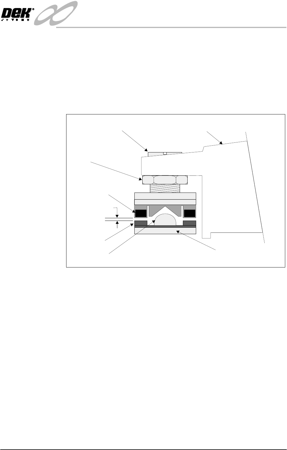
The head down position and therefore the printhead/table level is set by the
spigot around which the magnet is fixed. To ensure that the magnet does not
interfere with the level, a gap of 0.05mm to 0.3mm is set between magnet and
plate with the head down and latches turned off.
Figure 8-1 Printhead Left Hand Latch
Printhead Casting
Printhead Level Adjustment
Locknut
Locating Spigot
Aluminium Base Plate
Electro Magnet
0.05mm - 0.3mm
Sprung Latch