Specification SIPLACE CF-Medium.pdf - 第29页
28 Desc ription Tra nsp or ting Tra nsp or ting Tra nsp or ting Tra nsp or ting Use a for k lift wi th a l ifting force of 6 tons t o mo ve t he SIPL AC E CF plac ement machine. Forks 2 m long are req uired for a packed …
27
Technical Data:
Dimensions and Set-Up Conditions
Values
Length 1587 mm
Width excluding Waffle Pack Changer 2425 mm
Width including Waffle Pack Changer 2952 mm
Height from transport to warning lamp 1140 mm
Weight of basic module 1500 kg
Weight fully equipped excluding
Waffle Pack Changer 2000 kg
Weight fully equipped including
Waffle Pack Changer 2320 kg
Room temperature
Humidity
Between 15° and 35°C
30 - 80%, on average not higher
than 45%, so that no condensation
can ever form on the machine
Maximum noise development
74 dB
A
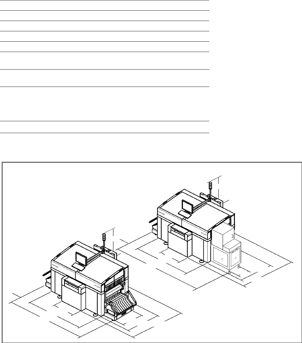
SIPLACE CF
1140
1140
252
252
740
740
1921
1921
2500
2952
1036
1036
1587
1587
350
Height of PCB transport
830
± 15 mm (standard)
900
± 15 mm (option)
930
± 15 mm (option)
950
± 15 mm (option) SMEMA
Foot height 120 mm
All units in mm
725
28
Description
Transporting
TransportingTransporting
Transporting
Use a fork lift with a lifting force
of 6 tons to move the SIPLACE CF
placement machine. Forks 2 m
long are required for a packed ma-
chine, 1.5 m for an unpacked one.
Pick the machine up with the fork
lift at the locations especially de-
signed and identified as being for
this purpose.
When setting up the SIPLACE CF,
make certain that the surface it is
placed on possesses the required
load bearing capacity.
Commissioning
CommissioningCommissioning
Commissioning
For commissioning, install the fol-
lowing components which were
not premounted upon delivery:
Monitor
Keyboard
Warning lamp
Component changeover tables.
Technical Data:
Transporting and Commissioning
Transport dimensions
Length with packing
Width with packing
Height with packing
2150 mm
1850 mm
1600 mm
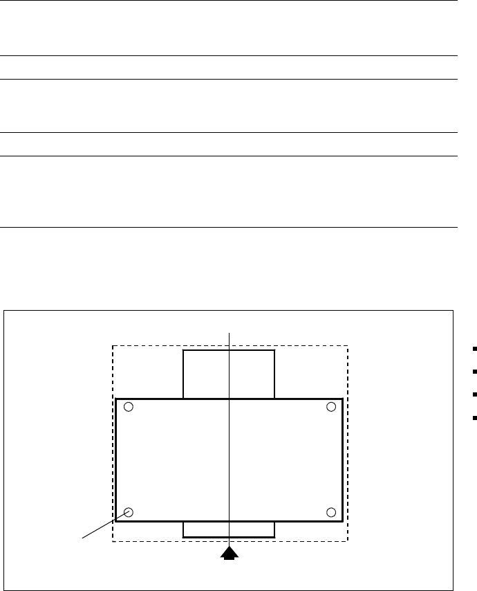
Center of gravity (X,Y coordinates) 0 mm, 0 mm
Floor load (more details about floor static characteristics on request)
Total weight of equipped machine 2 metric tons
Permissible surface load sub-floor
(load per unit area on mounting feet)
(based on assumed distribution of
machine weight to three machine legs
a
)
9 kg/cm
2
a) Worst case scenario; 4 legs per machine installed, area per leg: 104 cm
2
.
SIPLACE CF with Transportbox
Footprints
PCB Transport Direction
Dimension of
Transport Box
29
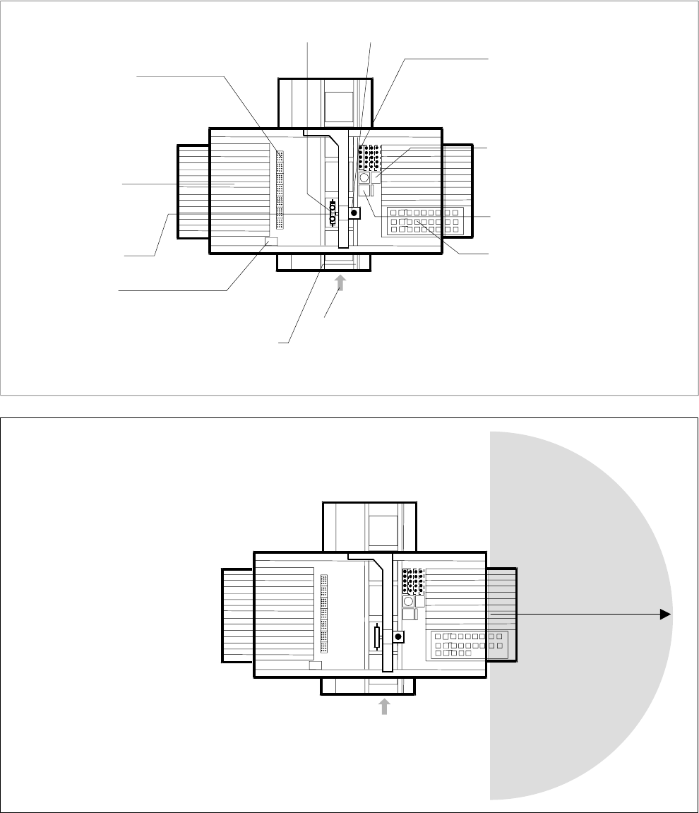
Left Side, Collect & Place Head
Collect & Place Head Pick & Place Head
Nozzle Changer
Changeover Table
with 20 Feeder
Places e.g. for Tapes,
Sticks and Bulk
Component Vision
on Collect & Place Head
Reject Bin
PCB Transport Direction
3-Section Conveyor With Automatic Width
Adjustment for PCBs from 50 x 50 mm
2
up to 508 x 460 mm
2
(2" x 2" up to 20" x 18")
Right Side, Pick & Place Head
Nozzle Changer 5 Nozzles (Capa-
bility to Extend to 20 Nozzles)
Reject Bin
Standard Vision Module
Feeder
e.g. for Tapes, Sticks, Bulk,
Manual Tray for Matrix Tray
(5 to 9 Feeder Places);
Waffle Pack Changer
(10 Feeder Places)
Possible Machine Configuration
Shunting Radius for
Changeover Table
1.20 m
PCB Transport Direction