4OM-1626-001_w.pdf - 第100页
4OM-1610 1-49 4. Consumables and Servicing Parts : Chap.1 4.2 List of Servicing Parts This component list is for the components for which maintenance is required in several years, for your reference. Note For the mainten…
4OM-1610
1-48
4. Consumables and Servicing Parts : Chap.1
0911-001
4. Consumables and Servicing Parts
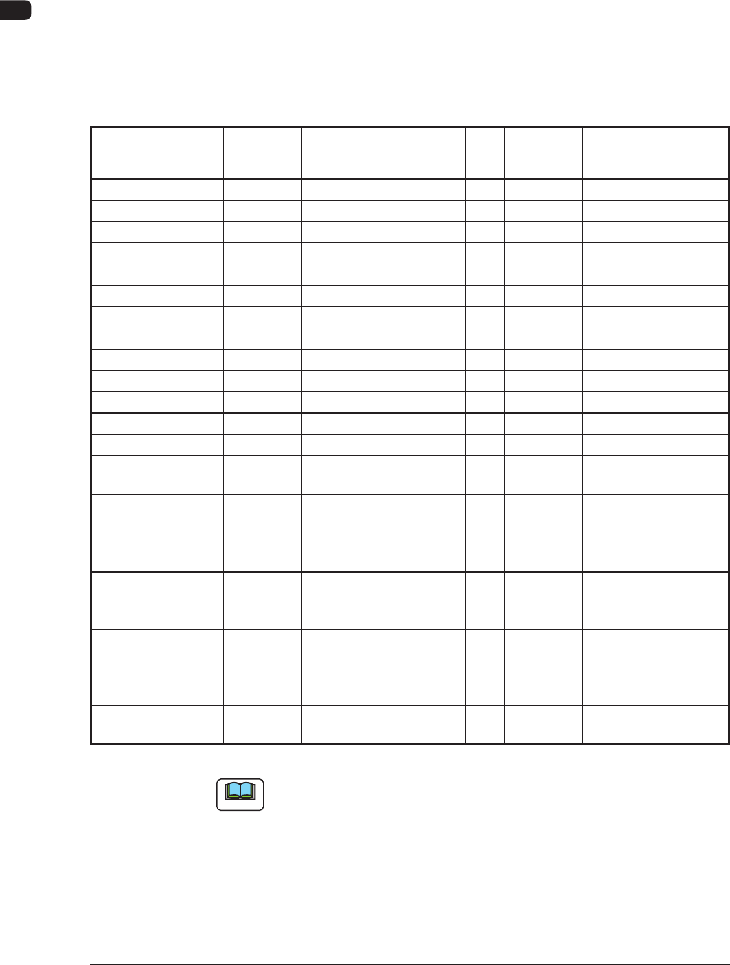
4.1 List of Consumables
This component list is for the components that would be worn within one year.
When any of these components are to be purchased, contact Marketing Dept. of
HITACHI High-Technologies or our sales agent.
Product Name Part No. Part Name 16
Q'ty
Recommended
number per year
note (a)
Exploded
Illustration
Remarks
Nozzle (HV81C) 0942910S ASSY, NOZZLE (HV81C) 30 30
Nozzle (HV02C) 0942910Y ASSY, NOZZLE (HV02C) 30 30
Nozzle (HV03C) 0942910Z ASSY, NOZZLE (HV03C) 30 30
Nozzle (HB03C) 0942J119 ASSY, NOZZLE (HB03C) 30 30
Nozzle (HB04C) 0942J11A ASSY, NOZZLE (HB04C) 30 30
Nozzle (HA04C) 0942910W ASSY, NOZZLE (HA04C) 30 30
Nozzle (HA05C) 0942910X ASSY, NOZZLE (HA05C) 30 30
Nozzle (HA09C) 0942910T ASSY, NOZZLE (HA09C) 30 30
Nozzle (PA05C) 0942J11C ASSY, NOZZLE (PA05C) 30 30
Nozzle (PA07C) 0942J11D ASSY, NOZZLE (PA07C) 30 30
Nozzle (HG31C) 0942910U ASSY, NOZZLE (HG31C) 30 30
Nozzle (HG51C) 0942910V ASSY, NOZZLE (HG51C) 30 30
Nozzle (HG21C) 0942911E ASSY, NOZZLE (HG21C) 30 30
Vacuum Filter 225B0572 AIR LINE EQPT 60 240 Fig. M-6,
Fig. SA-1
Fluorine Sheet 212A2743 GUIDE 2 2 Fig. DC-1,
Fig. DD-1
Urethane Clamp
ASSY
09207100
09207101
Sliding Type Clamper ASSY
Fixed Type Clamper ASSY
2
2
2
2
Fig. DC-4,
Fig. DD-4
Flat Ring 226A0256 SEAL 2 8 Fig. DC-3,
Fig. DD-3
Cutter Unit
Sliding Side
For the Roller
Cutter Blade
Cutter Blade Set Bolt
Cutter Blade Set Flat
Washer
213D1294
221AA121
221HA101
DISK
Socket Head Bolt
FW02W
4
16
8
4
16
8
Fig. DC-3,
Fig. DD-3
Note (c)
Nozzle Filter 225A0045 Nozzle Filter 30
(15)
960
(480)
Note (d)
T4A15
Note
(a) The recommended number of pieces is the value for reference only.
(b) Refer to "3. Maintenance Spots" for component replacement procedures.
(c) For the cutter blade replacement, consult with our service personnel
because it is a dangerous procedure.
When the cutter blade is replaced, also replace the bolt and at washer (A
at washer is attached to the lower blade, but not to the upper blade).
(d) The model names in brakets
are for the machine using the multi-functional
head.
4OM-1610
1-49
4. Consumables and Servicing Parts : Chap.1
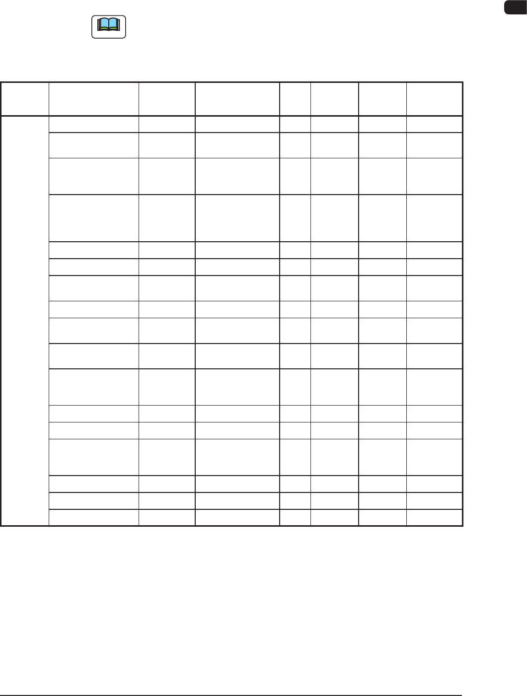
4.2 List of Servicing Parts
This component list is for the components for which maintenance is required in
several years, for your reference.
Note
For the maintenance procedure for the important maintenance components,
consult with our service personnel because high skill is required for such
maintenance.
Block
Name
Product Name Part No. Part Name Q'ty
Recommended
# of years
Note(a)
Exploded
Illustration
Remarks
Head
Section
Solenoid Valve 23D10016 ACCESSORY,SV 30 3 Fig. M-6
Nozzle Shaft ASSY
0916330J (*1)
0916331N (*2)
ASSY,GUIDE,LINEAR
30
Sets
- Fig. M-6 Note (c)
Hexagon Socket
Head Cap Screw
M2X4
221AA121 BOLT,HEX-SCT 30 - Fig. M-6 For Nozzle
Shaft Setup
Note (b)
O-Ring for Seal
Holder
226A0286
(S0-008-13)
0916D31E
(S0-010-12)
SEAL 30
90
2 Fig. M-6
Nozzle Shaft Spring 222M1462 SPRING,COMP 30 2 Fig. M-6
Packing for Nozzle 226A0279 SEAL 60 - Fig. M-6
O-Ring for Filter
SO-008-11A
226A0276 SEAL 60 2 Fig. M-6
Line Sensor 23G00313 SENSOR,PELEC 2 2 Fig. M-6
Diffusion Plate
(Outside)
213D1169 (*1)
0916D31G (*2)
DISK 2 - Fig. M-6
Diffusion Plate
(Inside)
213D1336 (*1)
0916D31F (*2)
DISK 2 - Fig. M-6
Hexagon Socket
Head Cap Screw
M1.6X4
221AA332 BOLT,HEX-SCT 14 - Fig. M-6 For Diffusion
Plate Setup
Note (b)
Top Block 211G6373 BLOCK 30 - Fig. M-6
Cam Follower (f2.5) 222H0163 CAMFOLLOWER 30 - Fig. M-6
Hexagon Socket
Head Cap Screw
M1.6X3
221AA330 BOLT,HEX-SCT 60 - Fig. M-6 For Top
Block Setup
Note (b)
Sensor PM-U24 23G20046 SENSOR,PHOTO 2 3 Fig. M-4
Sensor PM-L24 23G10059 SENSOR,PHOTO 10 3 Fig. M-4
Slip Ring 0916D30T COUPLING 2 2 Fig. M-5
T4A16
0911-001
4OM-1610
1-50
4. Consumables and Servicing Parts : Chap.1
Block
Name
Product Name Part No. Part Name Q'ty
Recommended
# of years
Note(a)
Exploded
Illustration
Remarks
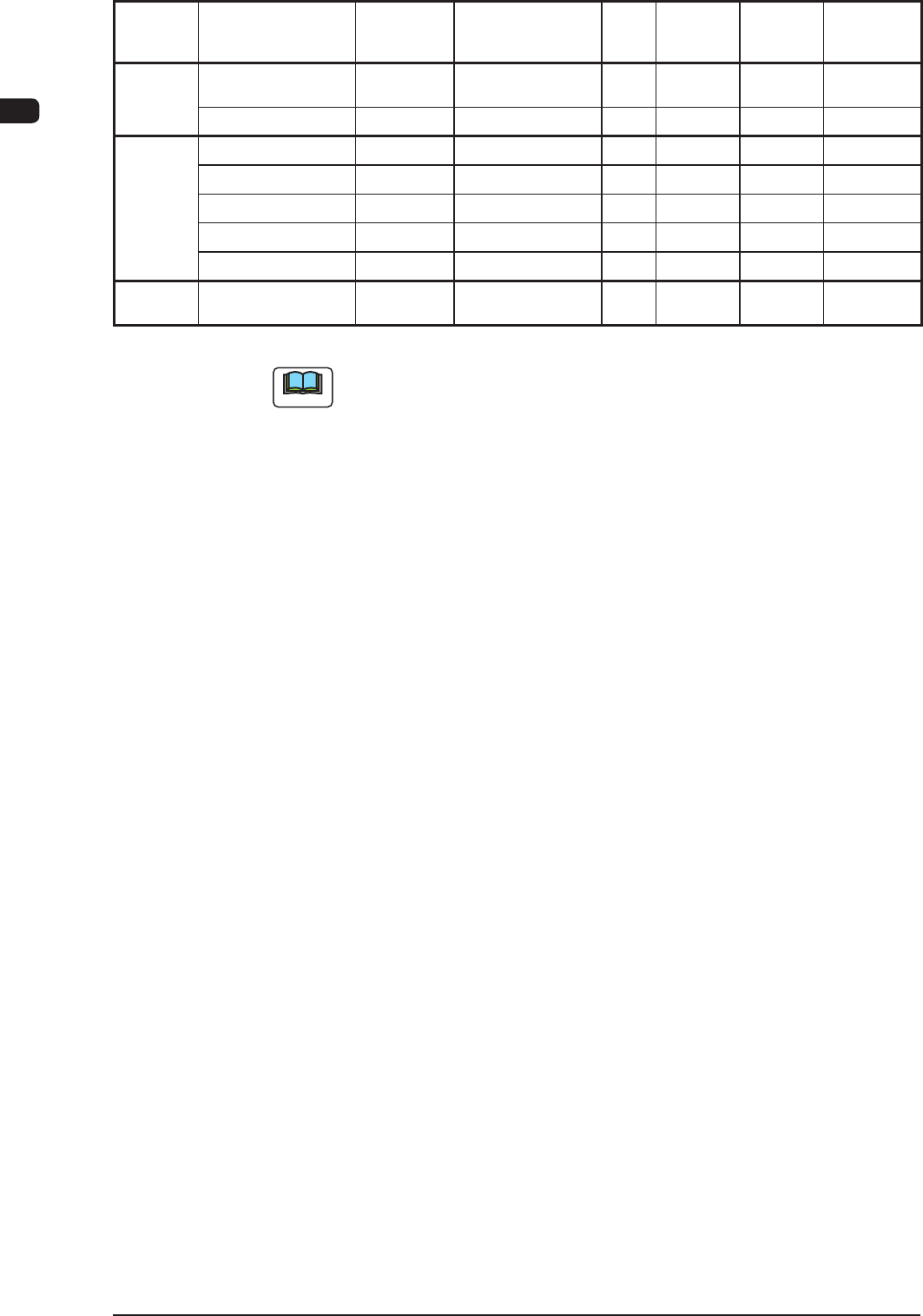
Main Unit Touch Panel
(Both Sides)
4U210135 EQUIPMENT 1 3 Fig. FA-1
Vacuum Pump 24A00420 VACUUM,PUMP 1 - Fig. B-3
Transfer
Unit
Transfer Pully 223Q0663 PULLEY,TIMING 12 5 -
Transfer Pully 223Q0755 PULLEY,TIMING 2 5 -
Transfer Pully 223M0059 PULLEY,TIMING 10 5 -
Transfer Belt 223L0383 BELT,TIMING 2 3 -
Transfer Belt 223L0384 BELT,TIMING 4 3 -
Cutter
Section
Cutter Block ASSY 09207106 GUIDE 2 2 -
T4A17
Note
(a) The recommended year of pieces is the value for reference only.
(b) Do not reuse any bolt removed during maintenance.
(c) *1 shows the case of using the diffuser plate (fan) and *2 shows the case of
not using such plate.
0911-001