YSi-X_HD_cwd_je.pdf - 第3页
YSi-X T ypeHD/HB T able of contents /目次 Over view -T ype HD- / 全体接続図 -Type HD - Over view -T ype HB- / 全体接続図 -Type HB- Power circuit -1-T ype HD / 電源回路図 -1-T ype HD Power circuit -1-T ype HB / 電源回路図 -1-T ype HB Power cir…
Safety.
To replace the purchased parts safely, be sure to comply with the following items.
However the following cannot cover all items regarding safety in detail. So it is
extremely important that the worker or person handling the machine make correct
decisions regarding safety.
CAUTION Machine operation of operator•Work is limited to maintenance and
safety skill.
Be sure to turn off the machine’s power supply before doing the exchange work.
Be sure to push the emergency stop SW, and do adjustment work under the
emergency stop condition.
Refer to the manual for the replacement work of each consumable part.
*
Safety alert symbols and signal words
CAUTION
Indicates a potentially hazardous situation which, if not avoided, may result in minor
injury, or material loss or damage to the machine. These points are important for
protecting the safety of the machine and data, etc.
安全について
お買い上げいただいたパーツを安全に交換していただくために、下記の事項は必ず守って作
業を行ってください。しかしながら、下記に全ての安全性に関する項目を細部にわたり網羅
することは困難です。従って作業者自身の安全に対する正確な判断が非常に大切な要素とな
りますことをご留意ください。
注意 作業者は本機の動作・メンテナンスに習熟していて安全に作業を行える方に限り
ます。
①交換作業は、マシンの電源を切ってから必ず行ってください。
②調整作業は、非常停止 SW を押し、非常停止状態で必ず行ってください。
③消耗品の交換、各メンテナンス作業についてはマニュアルをご参照ください。
※安全標記の 注意は取り扱いを誤った場合、傷害に至る可能性または物的損害の発生
が想定される内容を示しています。本体およびデータなどの損傷を防ぐために重要な注
意事項です。
YSi-X TypeHD/HB
Table of contents
/目次
Over view -Type HD-
/ 全体接続図 -Type
HD
-
Over view -Type HB-
/ 全体接続図 -Type HB-
Power circuit -1-Type HD
/ 電源回路図
-1-Type HD
Power circuit -1-Type HB
/ 電源回路図
-1-Type HB
Power circuit -2-
/ 電源回路図
-2-
Emergency circuit -1-
/ 非常停止回路図
-1-
Emergency circuit -2-
/ 非常停止回路図
-2-
Control box
/ コントローラー接続図
Servo amp -1-
/サーボアンプ接続図
-1-
Servo amp -2-
/サーボアンプ接続図
-2-
I/O conveyor -1-
/
I/O
コンベアー接続図
-1-
I/O conveyor -2-
/
I/O
コンベアー接続図
-2-
I/O conveyor -3-Type HD
/
I/O
コンベアー接続図
-3-Type HD
I/O conveyor -3-Type HB
/
I/O
コンベアー接続図
-3-Type HB
Head
/ ヘッド
Power transformer
/ 電源トランス接続図
Air circuit
/ エアー回路図
Wiring parts list
/ 配線部品表
P. 1
P. 2
P. 3
P. 4
P. 5
P. 6
P. 7
P. 8
P. 9
P.10
P. 11
P.12
P.13
P.14
P.15
P.16
P.17
P.18
Condential & Proprietary
Confidential & Proprietary
PAGE
Each Motors
K2
CH2 CH1
K1
EMERGENCY CIRCUIT
Safety Relay2
KM12
TRG
CAM
COMU
CONTROL BOX
HEAD UNIT
UPS
CAMERA UNIT
USB MEMORY
HDD
SERVO AMP
TC11 1.5KVA
QF12 15A
Main Breaker
2∼
Transformer
QF21 10A
Circuit
Protector
GB1
1∼ AC100V1∼ AC100V
UPS
TM11 4.50KVA
Main Switch
Main Breaker
NF11
POWER TRANSFORMER
TERMINAL
3∼
3∼ 3∼ AC200V
QS11 40A QF11 20A
Noise
Filter
QF31 10A
Circuit
ProtectorTransformer
Terminal
XB11
200/208/220/240
380/400/416
3∼ 50/60Hz
Rating 7.0KVA MAX.
LASER CONTROLLER
XT31
Terminal
LCD
+5VSB/2A
-12V/0.5A
ATX
Power Supply
3∼ AC200V
KM11
Contactor
Circuit
Protector
1∼ AC100V
3∼ AC200V
3∼ AC200V
GS21 300W 14A
Power Supply
DC24VA
QF22 5A
Circuit
Protector
DC24VA1
QF42 2A
Circuit
Circuit
Protector
QF41 10A
Protector
CVD+24V
KA10
SAFETY RELAY 3
DC24VA2
DRIVER
CONVEYOR MOTOR
SIGNAL TOWER
COVER S/W
EMG S/W
CONVEYOR MOTOR 30W
VALVE
SENSOR
FAN
COMU
I/O CONVEYOR BOARD
Power Supply
DC24VB
QF23 2A
Circuit
Protector
GS22 300W 14A
Power Supply
Power Supply
QF24 1A
DC12V
Circuit
Protector
DC5V
DC24VB
QF43 5A
Circuit
Protector
DC12V
QF44 1A
Circuit
Protector
DC5V
Fuse
TRG
DC24VB
X-RAY SOURCE
DC5V
DC12V
CAM
Safety Relay1
KM10
EMERGENCY CIRCUIT
K1CH1CH2K2
Protector Power Supply
QF25 1A GS25 50W 10A
Protector
DC-5V
DC-5V
DC-5V
POWER CIRCUIT
QF45 1A
See Page 16
See Page 6-7
See Page 9-10
See Page 8
See Page 11-14
See Page 6-7
See Page 15
See Page 15
See Page 13
GS23 50W 4.3A
FP Detector
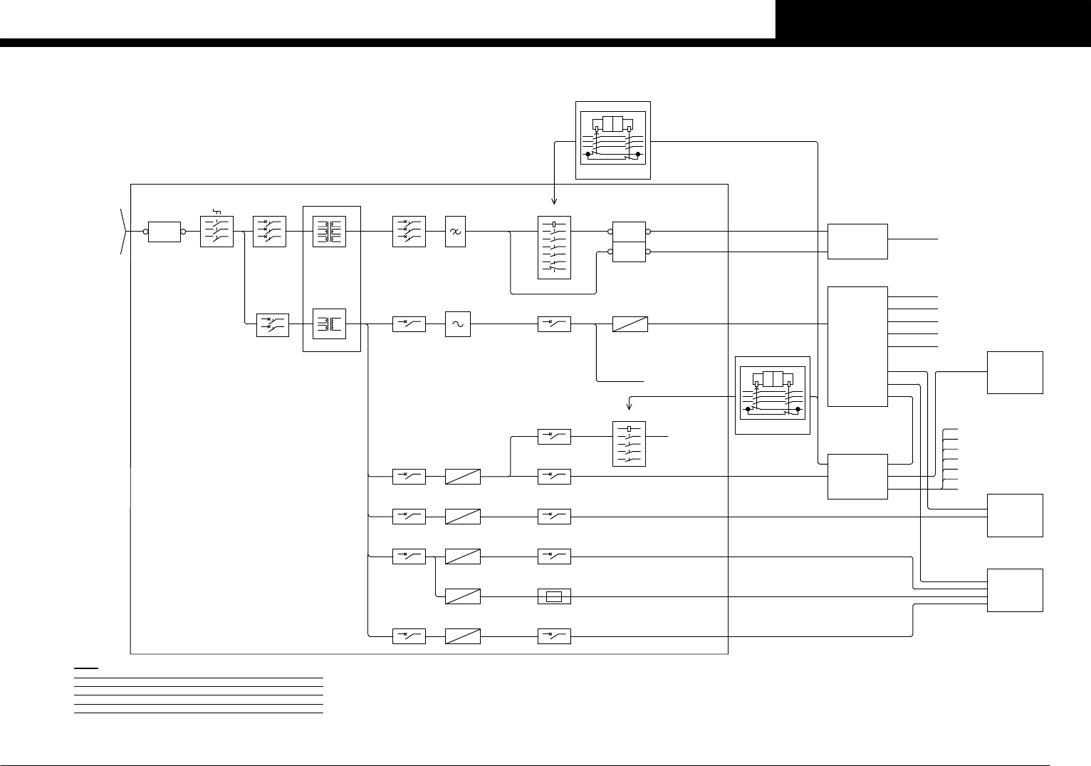
Notes
YSi-X has different camera variation.
Choose the interconnection diagram by camera type.
The details of camera type are as follows.
FU01 2A
See Page 3,5
GS24 15W 3A
QF51 4A GS31 400W +3.3V/20A
+5V/24A
+12V/30A
TYPE HB:Direct conversion panel method Long service life type
TYPE HD:FOS flat panel system High speed type
CC.V0
1
OVER VIEW -TYPE HD-
YSi-X HD/HB