MN_A_MANUAL.pdf - 第2页
Nitrogen Gas Circuit Electric Circuit Control Unit Ref. DI, DD, DDR, DM Stand Ref. DN-SE Nitrogen Handpiece Ref. T245-NA Nitrogen Flow Regulator Ref. MN-A Power Cord Socket Nitrogen Generator Ref. GN-A Compressed Air Inl…
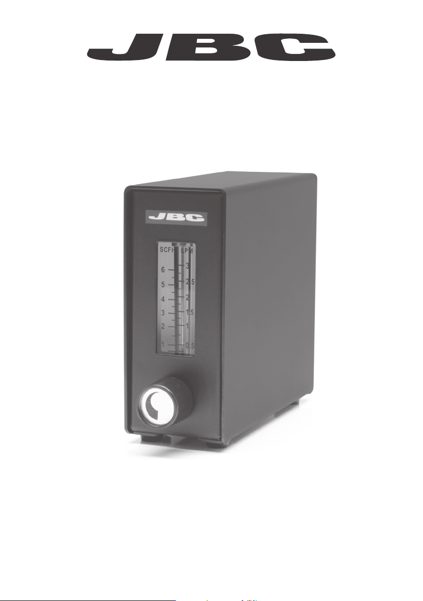
Nitrogen Flow Regulator
Ref. MN-A
www.jbctools.com
INSTRUCTION MANUAL
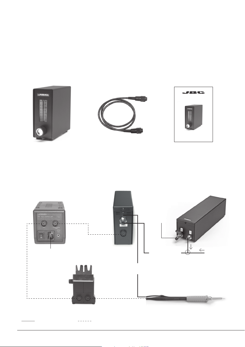
Nitrogen Gas Circuit Electric Circuit
Control Unit
Ref. DI, DD, DDR, DM
Stand
Ref. DN-SE
Nitrogen Handpiece
Ref. T245-NA
Nitrogen Flow Regulator
Ref. MN-A
Power
Cord
Socket
Nitrogen Generator
Ref. GN-A
Compressed
Air Inlet
or
Handpiece
N
2
tube
from N
2
net
Module cable
connector
Ref. 0010207
Stand cable connector R ef. 0 01128 3
N
2
pressure range
supply 3 to 6 bar
6 bar MAX
Nitrogen Flow Regulator
Ref. MN-A
Packing List
Connection
The following items should be included:
Nitrogen Flow
Regulator ........................ 1 unit
Ref. MN-A
Module Cable
connector ........................ 1 unit
Ref. 0010207
Manual ............................. 1 unit
Ref. 0009191
2
www.jbctools.com
Main menu
Exit
1 Reset settings
2
Station settings
3
Tool settings
Station settings
1 Temp unit
Celsius
2
Maximum temp 400
0
C
3
Minimum temp 200
0
C
4
Nitrogen mode ON
N
2
outlet
Description
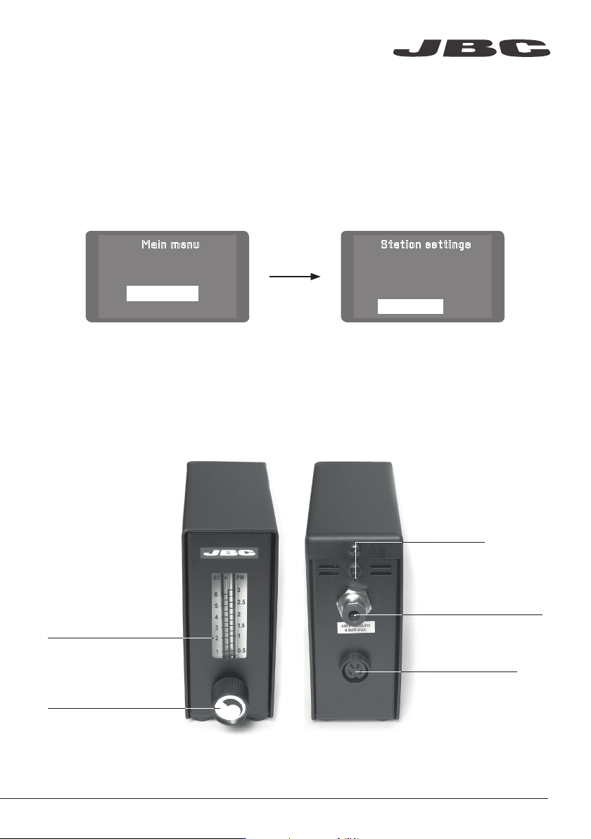
The MN is an electrovalve controlled by the soldering station that allows you to solder with nitrogen
with a minimum gas consumption.
Once the MN-A (Nitrogen Flow Regulator) has been connected to the Control Unit, enter into the
Station Settings menu and switch on the Nitrogen Mode.
The module will let the gas flow when taking out the tool from the stand and turning off when the
tool is again placed in its stand and reaches the sleep temperature.
Connection to
soldering station
Recommended N
2
flow:
1-2 liters/minute
N
2
flow control
Pressure range supply
3-6 bar
Maximum pressure
6 bar
www.jbctools.com
3