Printer 600 Board Support Tooling Module.pdf - 第2页
19.2 Technical Reference Manual Chapter Issue 2 May 03 %2$5'6 833257722/,1* 02'8/( ,1752'8&7 ,21 System Descriptio n The various tooling su pport opti ons are descri bed sep arately in t his ch apte…
%2$5'6833257722/,1*02'8/(
,1752'8&7,21
Chapter Issue 2 May 03 Technical Reference Manual 19.1
CHAPTER 19 BOARD SUPPORT TOOLING MODULE
INTRODUCTION The following board support tooling options are available for the machine:
• Magnetic Support Pillars (standard)
• Vacuum Box Tooling (optional)
• MultiFlex Tooling (optional)
• Dedicated Tooling Plate (optional)
• ProFlow Stencil Support (optional)
• FormFlex Tooling (optional)
Manual Tooling
Plate
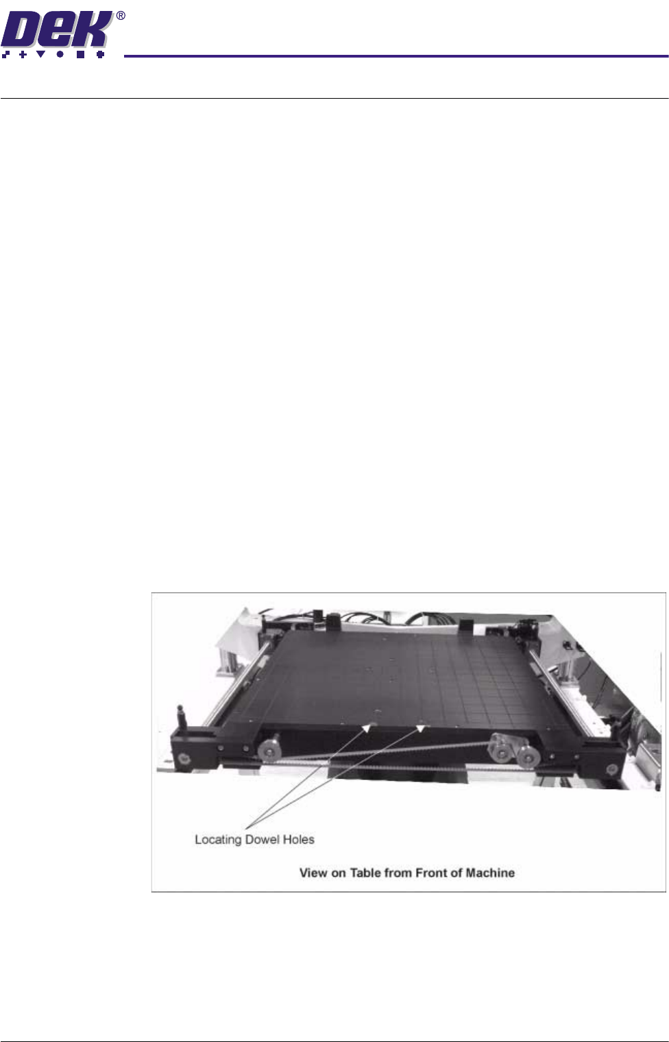
The manual tooling plate is the basic tooling module fitted to the machine rising
table. The following tooling options are fitted on the tooling plate:
• Magnetic Support Pillars
• Vacuum Box Tooling
• MultiFlex Tooling
• Dedicated Tooling Plate
• ProFlow Stencil Support
• FormFlex Tooling
Vacuum box, MultiFlex, Dedicated Tooling Plate and FormFlex tooling are
located on the plate by dowel holes. Magnetic support pins and ProFlow stencil
support are magnetically secured to the tooling plate.
Figure 19-1 Manual Tooling Plate

19.2 Technical Reference Manual Chapter Issue 2 May 03
%2$5'6833257722/,1*02'8/(
,1752'8&7,21
System
Description
The various tooling support options are described separately in this chapter.
The specifications for the options are tabulated below.
CAUTION
CAMERA DAMAGE.
Do not leave any unused tooling on the rising table in
the area behind the rear rail. If any object is left on the rising table outside
the board printing area, it could collide with the camera carriage as the
rising table moves to print height.
Tooling PCB Support Pin Diameter Remarks
Magnetic Support
Pillars
Magnetic Pins 19mm (0.75")
4mm (0.16")
Manual Changeover
Vacuum Box Vacuum Box N/A Manual Changeover
MultiFlex Pins 3mm (0.12") one
end tapered to
1mm diameter
5mm matrix of support pins, man-
ual setting and changeover,
optional vacuum hold down
Dedicated Tooling
Plate
Flat Plate N/A Dedicated to a specific board
size, manual changeover
FormFlex Self forming,
pneumatically
driven pin matrix
6mm 1 -10 modules
Each module - 22 x 2 rows of pins
at 12mm pitch
%2$5'6833257722/,1*02'8/(
0$*1(7,&68332573,//$56
Chapter Issue 2 May 03 Technical Reference Manual 19.3
MAGNETIC SUPPORT PILLARS
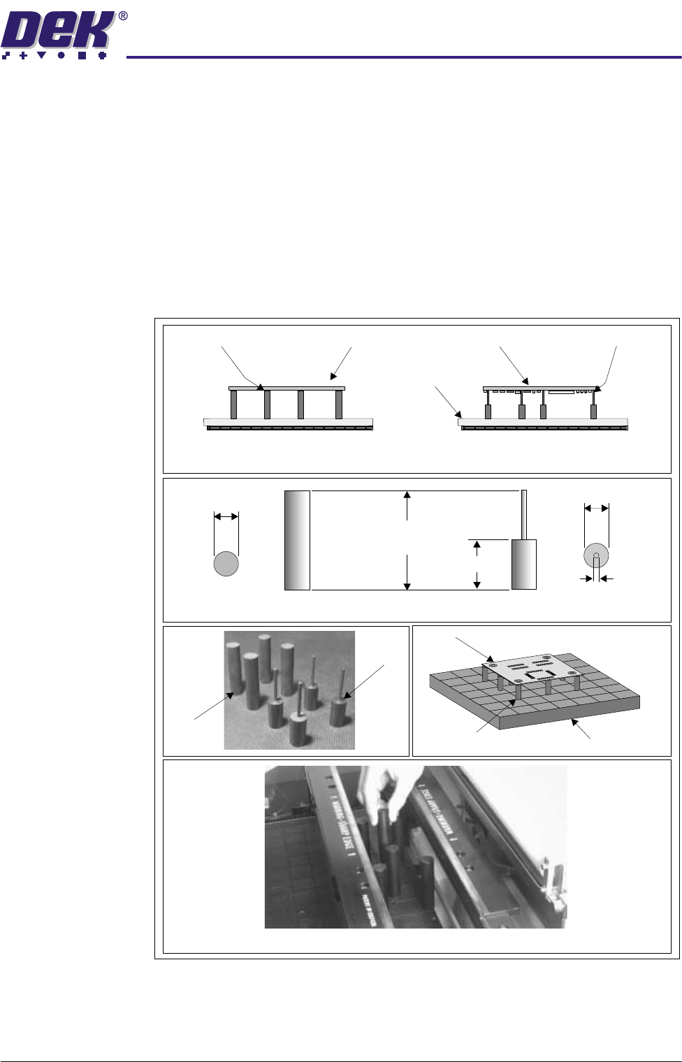
The magnetic support pillars are positioned on the manual tooling plate by the
operator. These pillars can be positioned anywhere under the board to provide
board support.
Two types of support pillar are provided:
• Standard flat-top pillars (19mm) for supporting boards which are not
populated on the underside.
• Pin-top pillars (4mm) for supporting boards which are populated on the
underside. The pins are positioned so that they fit between the compo-
nents on the underside of the board.
Figure 19-2 Magnetic Support Pillars
Fitment of Magnetic Pillars to Table
Flat-top Pillars used on
Unpopulated Board
Tooling Plate
Pin-top Pillars used on
Populated Board
Populated BoardFlat-top Pillars Pin-top PillarsUnpopulated Board
Pin-top
Pillars
Flat-top
Pillars
Board
Magnetic Pillars
Tooling Plate
19mm
81mm
(nominal)
38mm
19mm Dia.
4mm Dia.
Flat-top Pillar Dimensions
Pin-top Pillar Dimensions