00195655-04_SM_X-Series_FSE_en.pdf - 第29页
Service Work 3.3.1 Replacing the Trailing Cable Gantries Service Manual (internal ver sion) SIPLACE HF and X Series 29 ► Shorten the pneumatic hoses to the optimum length. Make sure that they are no t too long or too sho…
Service Work
Gantries 3.3.1 Replacing the Trailing Cable
28 Service Manual (internal version) SIPLACE HF and X Series
Installation
CAUTION
Handling
Handle the new trailing cable with care and enlist the help of a second person. Make sure that
the flat ribbon cable and the pneumatic hoses are not rubbed against any parts or folded. Look
out for sharp edges.
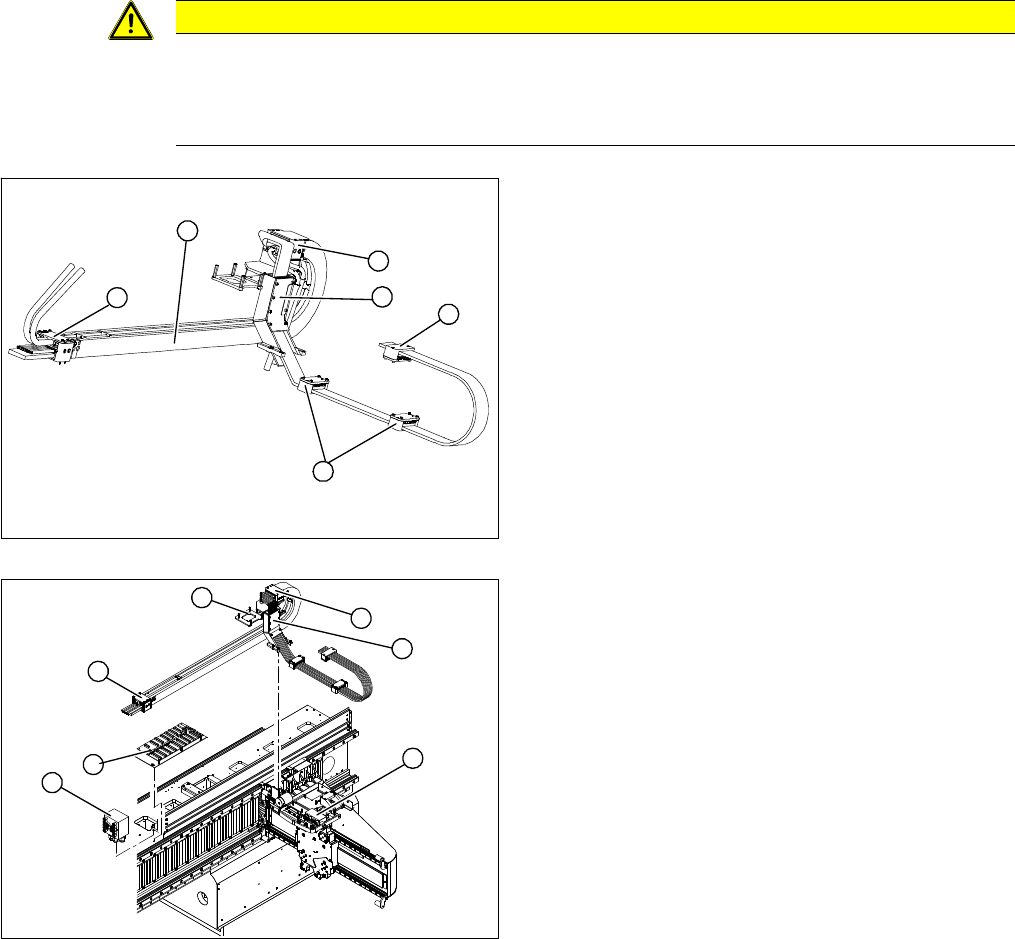
1. Complete trailing cable unit
2. Pressure plates on the power track chain.
3. Pressure plates on the gantry
4. Pressure plates on the head mount
5. Trailing cable console
► Carefully insert the new trailing cable (1) into the pre
-
scribed position. Make sure you do not twist it.
► Temporarily fasten the ends to the machine base
(e.g. by tying them).
► Fit the gantry interface board onto the cable clamp (4)
of the new trailing cable.
► Loosely fasten the trailing cable console (1) with a
screw.
► Clean the trailing cable contact surface on the ma
-
chine base with a dry cloth.
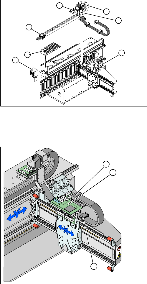
► Starting from the trailing cable console (1), run the flat
ribbon cable and hoses to the appropriate connec
-
tions:
⇨ Pneumatic distributor (2)
⇨ Trailing unit interface gantry (3)
⇨ Gantry interface (4)
⇨ Gantry distributor (5)
► Reconnect to the electricity supply. Observe the cor
-
rect connector assignment.
2
5
1
4
3
2
2
5
4
6
6
1
3
Service Work
3.3.1 Replacing the Trailing Cable Gantries
Service Manual (internal version) SIPLACE HF and X Series 29
► Shorten the pneumatic hoses to the optimum length.
Make sure that they are not too long or too short.
They must engage firmly but should not buckle.
► Reconnect to the compressed air supply. Observe
the correct connector assignment.
► Loosely fasten the pressure plates (6) to the machine
base.
► Check that the power track chain can run along the
top of the machine base without obstruction. Move
the Y axis back and forth to check this.
► If necessary, correct at the trailing cable console (1)
and at the pressure plates.
► Fix the two pressure plates (6) and the trailing cable
console (1). Use Loctite 241 locking varnish to secure
them.
► Tighten the fastening screws for the trailing cable
console (1) crosswise.
► Reconnect the cooling tubes to the Y motor.
► Fit the 3 pressure plates (1) at the gantry and head
mount (2).
► You will need to replace the cable supports for
SIPLACE HF machines up to MA219. See also
"3.3.1.5.4 Conversion for SIPLACE HF up to A 219"
[➙30].
► Fit the head board (3). Make sure you do not lose the
contact disks or spacer bolts.
► Plug in all connections/terminals. Observe the cor
-
rect connector assignment.
► Fasten new cable ties at the original points.
► Replace all dismantled cover plates in their original
positions.
2
5
4
6
6
1
3
5
1
3
2
Service Work
Gantries 3.3.1 Replacing the Trailing Cable
30 Service Manual (internal version) SIPLACE HF and X Series
Conversion for SIPLACE HF up to A 219
These versions of the trailing cable can also be used with SIPLACE HF machines up to machine number
A-219, in conjunction with the "Trailing cable retrofit kit" 03046248-01.
▪ Trailing cable for HF machines with one gantry
– [03039706S01] Trailing cable analog 1P
▪ Trailing cable for HF machines with two gantries in uneven locations (1 and 3)
– [03039708S01] Trailing cable analog 2P U
▪ Trailing cable for HF machines with two gantries in even locations (2 and 4)
– [03039709S01] Trailing cable analog 2P G
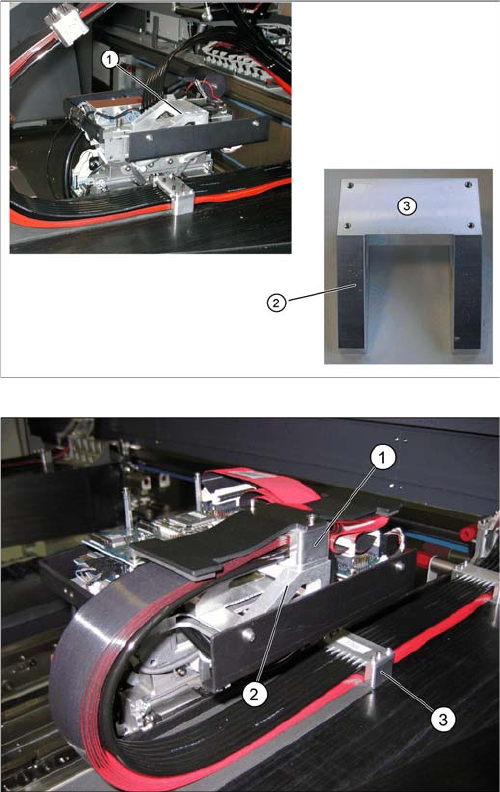
The difference lies in the fact that the new pressure plate
can no longer be fastened to the existing cable support.
The old cable support (1) therefore needs to be replaced
with a new one.
► Replace the old cable support (1) with the new cable
support (2) from the retrofit kit. The new cable sup
-
port has four drilled holes (3) for fastening the new
pressure plate.
► Fit the pressure plate for the new trailing cable onto
the new cable support, with the four M3x35 screws
from the retrofit kit.
► If the pressure plate on the gantry does not fit into the
existing holes drilled, loosen the clamp on the pres
-
sure plate and shift it accordingly.
► Tighten the clamp again and fit the pressure plate at
the correct position of the gantry drillings.