True-Flat-Paper-US-Tech_BTU.pdf - 第2页
reflow process. The objective of negative pressure reflow is to generate a continuous suction from the start of heating to the end of the cooling process within the heated chamber. A slow cooling rate profile is adopted …
T
he miniaturization of electronic
components has led to the use of
copper pillars, smaller bump sizes
and narrower pitches. This has resulted
in lower flexibility of joints and more
sensitivity to the influence of coefficient
of thermal expansion (CTE) mismatch.
Component tilt, open solder joints and
cracks with the use of extreme low-K
(ELK) dielectric materials are defects
that increase with this trend.
BTU’s solution, TrueFlat tech-
nology, which uses negative pressure
reflow is designed to alleviate yield
losses due to CTE mismatch during
reflow soldering. Advanced thermal
control (ATC) is introduced to control
the rates of heat transfer for processes
sensitive to abrupt expansion and con-
traction.
ATC is an enhancement of exist-
ing control for heating and cooling
rates to achieve continuous, uniform
heat transfer. This provides the abili-
ty to control the abrupt expansion and
contraction stress produced by micro
spikes.
Challenges of Miniaturization
Silicon flip chip and thin organic
substrates have significantly different
CTEs. CTE mismatch for flip chip on
thin substrates has been a challenge for
more than 10 years. Controlling defects
in mass reflow caused by warpage- and
CTE stress-related cracks has long been
the focus of reflow process engineers.
Other reflow techniques, such as ther-
mal compression bonding, are available.
However, these processes are expensive
and have low throughput, which makes
mass reflow a preferred process.
Existing mass reflow methods to
alleviate the effects of CTE mismatch
consist of a solid carrier acting as a heat
spreader, a cover plate to attempt to
hold down the substrate during reflow
and the use of a slow cooling process to
control the rate of contraction. This
method is being challenged as miniatur-
ization continues.
The use of a reduced or negative
pressure (pressure below atmosphere)
below the carrier throughout the
entire reflow process enhances the
contact of the substrate on the carrier
and helps to keep the substrate flat.
This enhances localized contact
below the chip, where a cover plate is
not effective. More effective heat
spreading produces greater tempera-
ture homogeneity and reduces the
impact of abrupt expansion and con-
traction due to CTE mismatch.
Ensuring contact with the carrier
helps to keep the substrate flat and
reduces deformation.
Negative Pressure Reflow
To demonstrate experimentally,
this requires two stages. The first
stage is to ensure effective contact of
the substrate to carrier. The second is
to control the heating rates for the
Reducing CTE Mismatch Defects in
Flip Chip Reflow
By Patrick Gao, Shoubing Ni, Thomas Tong, and Joe Yang, BTU International, Inc.
Reprinted with permission from the May, 2019 issue of ...
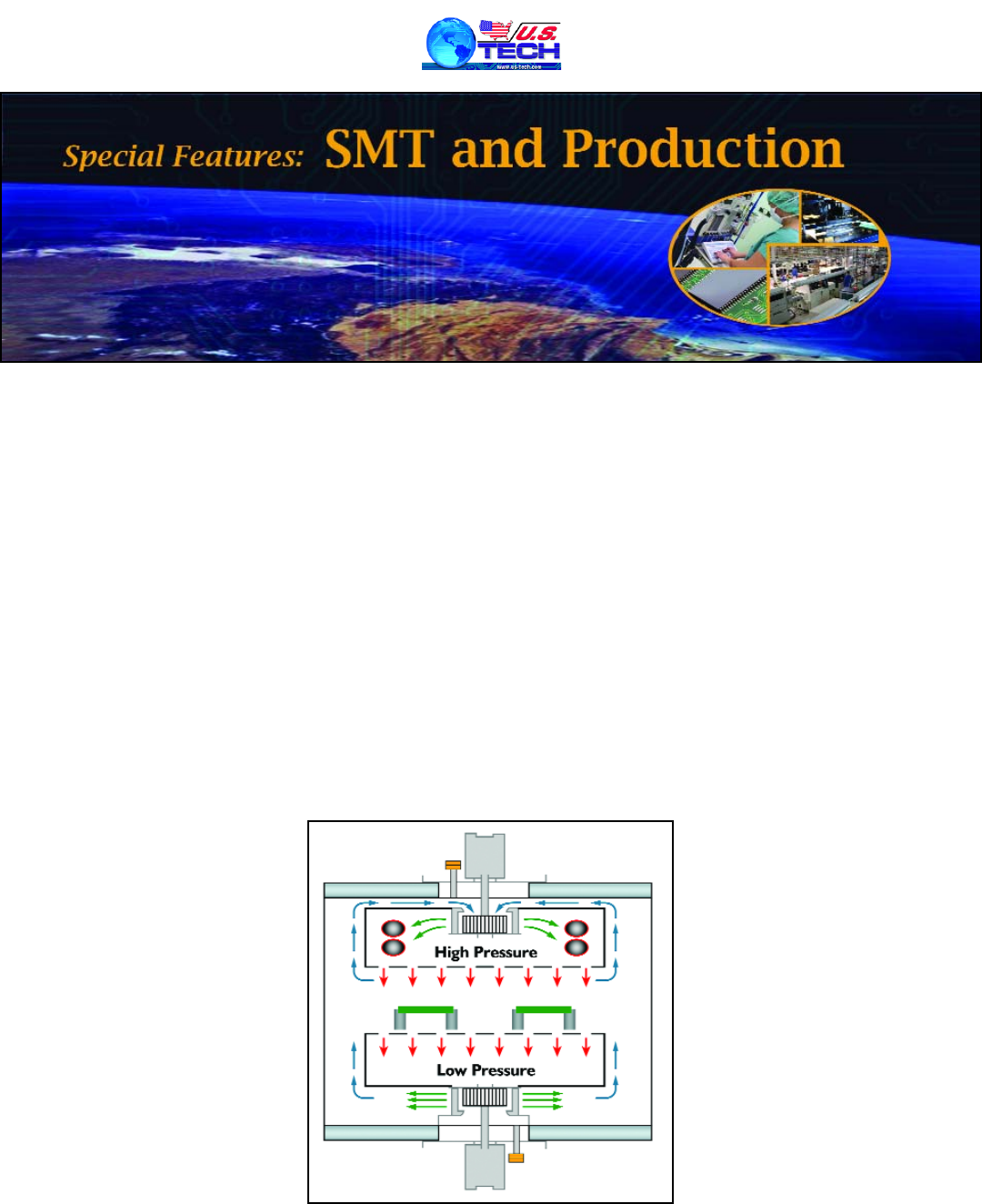
Figure 1: Negative pressure reflow design.
reflow process. The objective of negative pressure reflow is to
generate a continuous suction from the start of heating to the
end of the cooling process within the heated chamber. A slow
cooling rate profile is adopted to minimize the impact of heat
spikes.
Figure 1 demonstrates the gas flow to generate effective
suction with edge rail conveyors. Redirection of gas flow on
the bottom of the process produces a suction box effect, and a
pressure below atmosphere, directly below the conveyor and
product
— hence the name “negative pressure reflow.”
The carrier design is important for uniform suction and
heating. A large suction hole size creates localized heat spikes.
The recommended layout is 0.04 in. (1 mm) diameter hole grid
below the substrate. There are window and mesh top covers
used in standard reflow ovens without suction. Mesh has the
advantage of holding down the edges of each chip but has less
flexibility and costs much more to produce.
Window covers hold down the edges of the sub-
strate and allow different layouts of chips on the
substrate. The center of the substrate is subject-
ed to deformation, as there is nothing ensuring
proper contact of the substrate to the carrier.
Pressure should be measured below the
carrier with a room temperature fixture over-
laid onto a ramp to spike (RTS) slow-cool tem-
perature profile
— measured in the same oven.
If the suction remains effective throughout the
process, it ensures intimate contact of the sub-
strate with the carrier above the Tg of the sub-
strate where the deformation is at its worst.
As temperature increases, suction force will
be reduced. This is a normal phenomenon as air
density increases with higher temperature,
reducing the efficiency of suction. With a normal
tin-silver-copper (SAC) reflow profile, the suction
reduction will be about 30 percent. However, this
is still sufficient to keep the hotter substrate held
down on the carrier. This can be demonstrated
with a thermocouple (TC) mounted on the carrier,
just below the TC on the top side of the substrate.
The top of Figure 2 shows the heating of the substrate as
humps, due to the absence of the heat spreading effect as the
substrate lifts off from the carrier as it deforms. With suction,
effective heat spreading occurs, which evens
out the temperature.
Advanced Thermal Control (ATC)
Below are the heat transfer formulas related to mass
reflow ovens.
Convection heat delivered:
Target heat absorbed:
This produces S-curve heat transfer characteristics and
the heating rate will reduce when the target temperature
approaches the convection temperature. Common parameters
for mass reflow ovens based on the parameters for the above
transfer are: M = mass of the product and car-
rier; C
p = specific heat capacity of carrier; A =
exposure area; t = exposure time; H = coeffi-
cient of convection; and T = temperature.
Control of the heating rate can be
achieved by adjusting the reflow parameters.
The mass (M) of the product is an important
factor. It is necessary to reduce excess area
and weight of the carrier to minimize effects of
forward heat sinking and backward conduc-
tion, which impact the thermal uniformity
along the direction of flow.
It is typical to see the rear of the product
with a higher temperature than the leading
edge. The rear will act as a heat sink for the
leading edge, while the leading edge will con-
duct heat to the rear as it gets hotter. This
effect can be reduced with smaller tempera-
ture setting differences between the zones and
avoiding high ramp rates, but may require
longer zones or a longer oven.
With the oven size, conveyor speed and the product and
carrier mass held as constant, the next parameter to investi-
gate is the coefficient of convection (H). The variables for con-
vection heat transfer will be the area of coverage and impinge-
ment pressure. Plenum orifice size and distance from target
will determine the impingement force on the product. By opti-
mizing the orifice size, distribution and distance from product,
the thermal transfer rate can be optimized
to a preferred condition. This creates a con-
www.us
-tech.com
Figure 2: Window cover without suction (top)
and with suction (bottom).
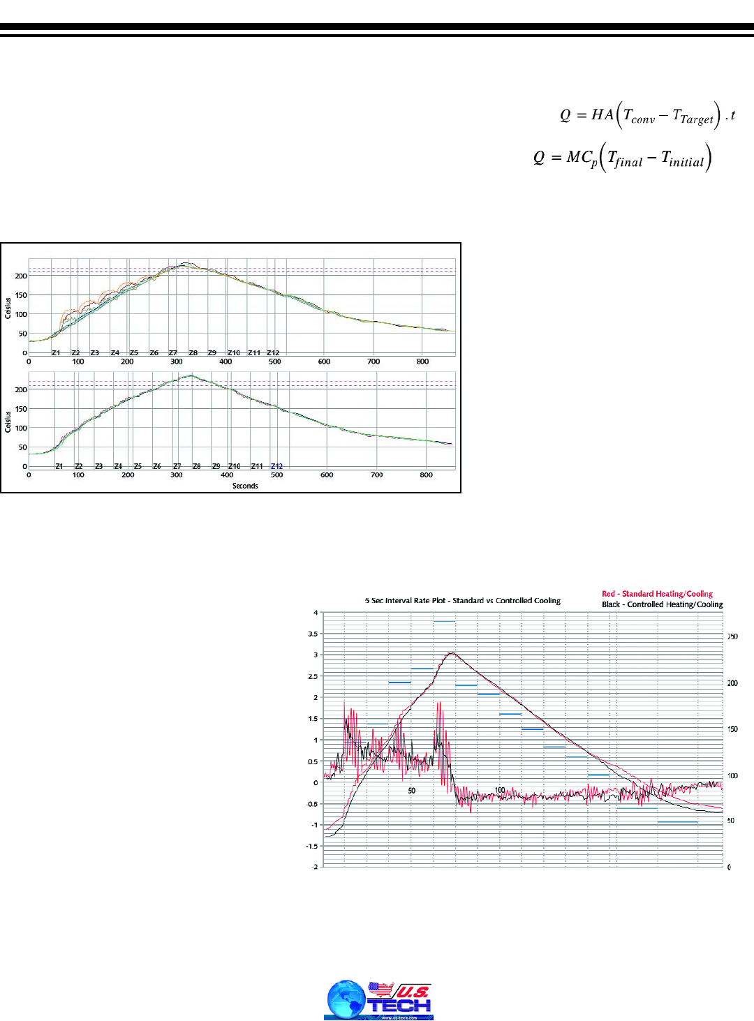
Figure 3: Profile comparison — standard vs. ATC.

trolled heating and cooling rate for the reflow process.
Figure 3 (page 67) displays the profiles with similar set-
tings and some fine-tuning to accommodate the critical areas
to control reflow and CTE differences. Unformed joints are
not sensitive to CTE mismatch during heating. The area of
critical control starts from the reflow ramp at zone 5 to the
end of the oven cooling zones. The calculations for heating
and cooling rates are made over five second intervals.
The control of the time above liquidus (TAL) is believed
to influence the spread size of the solder joint. This deter-
mines the area of interface between the substrate and bump
and will be more prone to cracks if the timing is too long.
Typical TAL values are between 50 and 60 seconds.
It can be seen in Figure 3 that the cooling rates achieved
with the controlled cooling from ATC are more consistent,
even as those compared to the standard PYRAMAX TrueFlat
oven. These spikes over short durations of five seconds are
called micro spikes. How critical are these micro spikes to the
reflow process?
If the pitch is wide, such as
≥
120 micron copper pillars
or simply by using soft solder bumps, the effect of these
spikes may be less detrimental. With further miniaturiza-
tion, brittle ELK dielectric with copper pillars and much
finer pitch means less flexibility and more sensitivity to
CTE-related cracks. Such products will require tighter con-
trol of the cooling rate.
TrueFlat negative pressure reflow technology ensures
that thin substrates on carriers are kept flat to reduce die tilt
and in direct contact for effective heat spreading during the
reflow process. ATC complements TrueFlat technology in
reducing micro spikes for optimal control of CTE mismatch-
related defects.
Contact: BTU International, Inc., 23 Esquire Road,
North Billerica, MA 01862 978-667-4111
Web: www.btu.com
See at NEPCON China,
Booth 1E50, and at SMTconnect,
Hall 4 Booth 551
www.us
-tech.com