manual-ph218-thermocouple-type-k-jbc-0028991_ID-222845_EN.pdf - 第2页
2 40 mm 50 mm 60 mm 80 mm 100 mm 130 mm 130 mm par a manuales - c olor g r is 200 mm 300 mm Features and Connections Clamp for better fastening PH21 8 Thermocouple T y pe K ................................ 1 u n i t Manu…
INSTRUCTION MANUAL
Thermocouple Type K
PH218
2
40 mm
50 mm
60 mm
80 mm
100 mm
130 mm
130 mm
para manuales - color gris
200 mm
300 mm
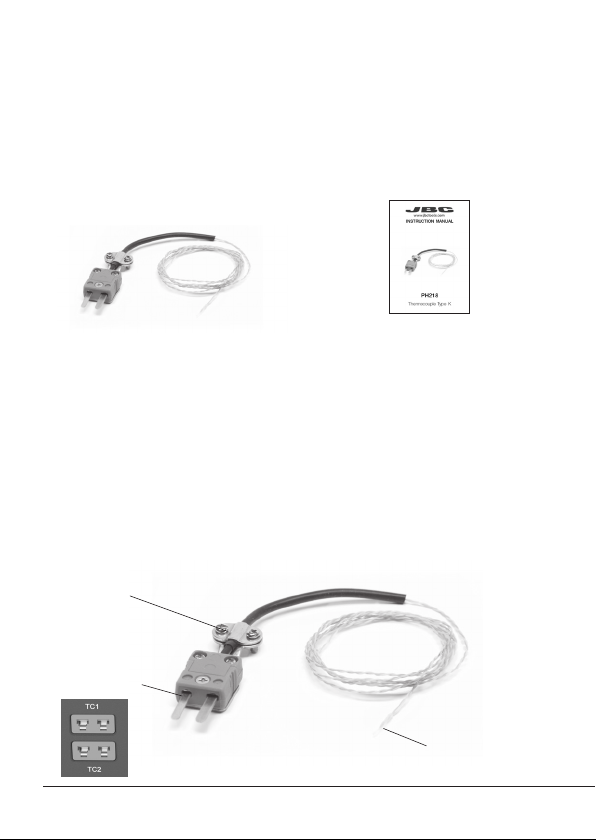
Features and Connections
Clamp for
better fastening
PH218 Thermocouple
Type K ................................ 1 unit
Manual ............................... 1 unit
Ref. 0028991
The following items are included:
Packing List
This manual corresponds to the following references:
PH218
Connection to
JBC device.
The Thermocouple Type K reads the temperature on a specific point
of the PCB.
PH218 helps to manage the temperature profiles when used with
JBC’s preheaters and hot air stations. It also works with TID, JBC’s
digital thermometer.
Fix the wire end with
kapton tape on the
PCB/Component
PHXLE
PHXL-SA
PHB-SA
PHS-SA
PHN-SA
PHBE DESPIECE PHB
PHSE
PHNE
OK
14:15
20
º
C
Power
45%
TC1
45
º
C
Selected 120
º
C
TC2
P
100
º
C
20
º
C
TC3
P
100
º
C
20
º
C
TC4
P
100
º
C
14:15
20
º
C
Power
45%
Selected power
45
%
TC1
P
100
º
C
20
º
C
TC3
P
100
º
C
20
º
C
TC4
P
100
º
C
20
º
C
TC2
P
100
º
C
14:15
20
º
C
T1
23
º
C
20
5’ 8’
º
C
120
º
C
T3
24
º
C
T7
StopPROFILE1
200
100
14:15
31
º
C
27
º
C
TC1
TC2
StopPROFILE1
200
100
14:15
200
150
100
50
300
250
14:15
5m 00s
120
º
C
PROFILE1
200
100
14:15
30
º
C
Power
45%
Selected power
45
%
TC1
C
100
º
C
---
º
C
TC2
P
100
º
C
0 60 120 180 240 300
Point
2/3
Temp Time
2m 00s
14:15
20
º
C
20
º
C
TC1
TC2
20
º
C
TC3
20
º
C
TC4
StopPROFILE1
200
100
Ext. Temp [ºC]Power [%]
14:15
20
º
C
Power
45%
TC1
45
º
C
Selected 120
º
C
TC2
P
100
º
C
20
º
C
TC3
P
100
º
C
20
º
C
TC4
P
100
º
C
14:15
20
º
C
Power
45%
TC1
45
º
C
Selected 120
º
C
Max. Rate
1.6ºC/s
Max. Rate
1.6ºC/s
TC2
C
100
º
C
20
º
C
TC3
P
100
º
C
20
º
C
TC4
P
100
º
C
14:15
20
º
C
Power
45%
Selected power
45
%
14:15
TC5
P
100
º
C
20
º
C
TC7
P
100
º
C
20
º
C
TC8
P
100
º
C
20
º
C
TC6
P
100
º
C
20
º
C
TC5
P
100
º
C
14:15
20
º
C
Power
45%
TC1
25
º
C
Selected 120
º
C
TC2
P
100
º
C
14:15
20
º
C
Power
45%
TC1
25
º
C
Selected 120
º
C
TC2
P
100
º
C
14:15
20
º
C
Power
45%
TC1
45
º
C
Selected 120
º
C
TC2
C
100
º
C
20
º
C
TC3
P
100
º
C
20
º
C
TC4
P
100
º
C
20
º
C
TC5
P
100
º
C
20
5’ 8’
º
C
120
º
C
80
º
C
100
º
C
5’ 8’5’30”3’30” 8’
20
º
C
120
º
C
80
º
C
TC1
TC2
TC3
TC4
ROBOT
AUX.
PEDAL
Hot
Zone B
Zone A
Zone A
Zone B
Hot
Hot
Zone B
Zone A
Zone A
Zone B
Hot
TC1
TC2
TC3
TC4
ROBOT
AUX.
PEDAL
detalle parte trasera
TC1
TC2
TC3
TC4
ROBOT
AUX.
PEDAL
TC1
TC2
TC3
TC4
ROBOT
AUX.
PEDAL
Hot
Zone B
Zone A
Zone A
Zone B
Hot
Hot
Zone B
Hot
Zone B
Zone A
Zone A
Max. Rate
1.6ºC/s
Max. Rate
1.6ºC/s
Max. Rate
1.6ºC/s
Max. Rate
1.6ºC/s
Work mode
Mode
Time to stop
Thermocouples
Max Rate
Back
None
2min
Temp.
14:15
Work mode
Mode
Time to stop
Thermocouples
Max Rate
Back
None
2min
Temp.
1.6ºC/s
Max Rate
Min 0.1ºC/s Max 2.0ºC/s
3
40 mm
50 mm
60 mm
80 mm
100 mm
130 mm
130 mm
para manuales - color gris
200 mm
300 mm
Recommendations
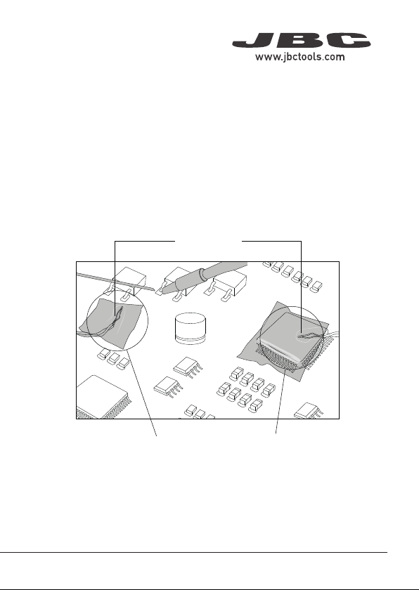
The use of kapton tape is recomended to fix the end of the thermocouple
wire onto the PCB.
Place the control thermocouple as near as possible to the component
being soldered/reworked (1).
If there are any sensitive components, use a second thermocouple
(2) as protection.
Fixed with Kapton
Tape
(2) Protection
Thermocouple
(1) Control
Thermocouple
It is not recommended to exceed ramp-up rates over 3 - 4 °C / sec
(5 - 7 °F / sec) so as to reduce the risk of thermal stress on the PCB.