ELA Installation.pdf - 第39页
MACHI NE PRE PARAT ION MACHI NE ASSE MBLY Chapter Issu e 3 Jun 01 Installati on Manua l 5.13 MA CHINE A SSEMBL Y Assemble the machine components a nd assemblies remov ed for transportation to the machine, as listed in th…

MACHINE PREPARATION
MACHINE RELOCATION
5.12 Installation Manual Chapter Issue 3 Jun 01
Vacuum Filtration
Unit Option
In accordance with customer requirements, the optional onboard vacuum filtra-
tion unit is fitted to the machine in one of two configurations:
• 110 Volt Unit
• 230 Volt Unit
CAUTION
LOW VOLTAGE FILTRATION UNIT. Filtration unit internal fuse (8A)
is liable to rupture if low voltage unit is connected to a high voltage factory
supply.
110 Volt Unit If the printing machine is reconfigured from a low voltage factory supply setting,
to that of a higher voltage setting. The low volt optional vacuum filtration unit
(DEK Part No. 163557), must be replaced with a high voltage unit (Dek Part
No.163558).
NOTE
No apparent damage to the unit would occur, with the exception of the supply
cable temperature increasing and consequent rupturing of the unit internal fuse
(10A).
230 Volt Unit If the printing machine is reconfigured from a high voltage factory supply
setting, to a lower voltage setting. The high volt vacuum filtration unit must be
replaced with a low voltage unit.
NOTE
No apparent damage to the unit would occur, however the unit performance
would be greatly diminished.
MACHINE PREPARATION
MACHINE ASSEMBLY
Chapter Issue 3 Jun 01 Installation Manual 5.13
MACHINE ASSEMBLY
Assemble the machine components and assemblies removed for transportation
to the machine, as listed in the Machine Components table in Chapter 4.
Monitor and IR
Receiver
1. Position the monitor centrally on the top of the machine.
2. Connect the monitor as follows:
a. Connect 14SK10 (power) from the cover connector plate to the monitor.
b. Connect 14PL31 from the monitor to 14SK31 on the cover connector
plate.
c. Connect the infra red receiver unit leads 14PL32 (keyboard) and 14PL33
(mouse) to 14SK32 and 14SK33 respectively on the cover connector plate.
Tricolour Beacon 1. Assemble the tricolour beacon assembly to the bracket on the right hand side
of the machine.
2. Connect the tricolour beacon 14PL07 to 14SK07 at the beacon bracket.
ProFlow For ProFlow only machines:
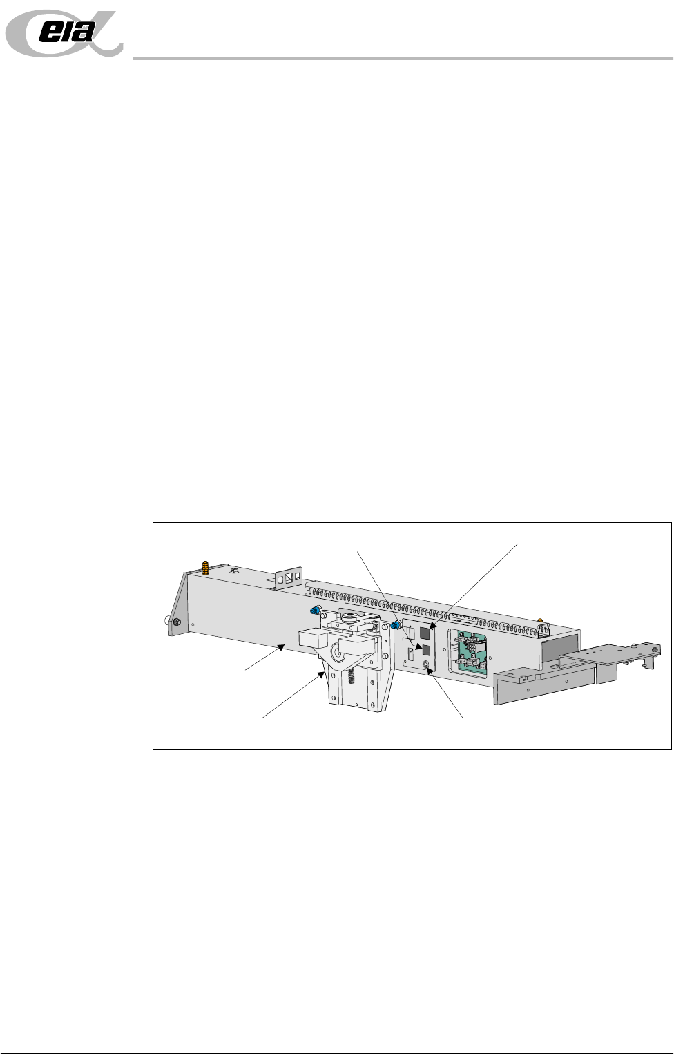
1. Fit the following ProFlow mechanism connectors (figure below refers):
• ProFlow motor connector 9PL17 into 9 way socket 9SK17
• ProFlow home sensor connector 9PL08 into 6 way socket 9SK08
Print Carriage
ProFlow (Printhead) Mechanism
9SK08 (Home Sensor)
ProFlow Fitted Socket
9SK17 (ProFlow Motor)
MACHINE PREPARATION
MACHINE ASSEMBLY
5.14 Installation Manual Chapter Issue 3 Jun 01
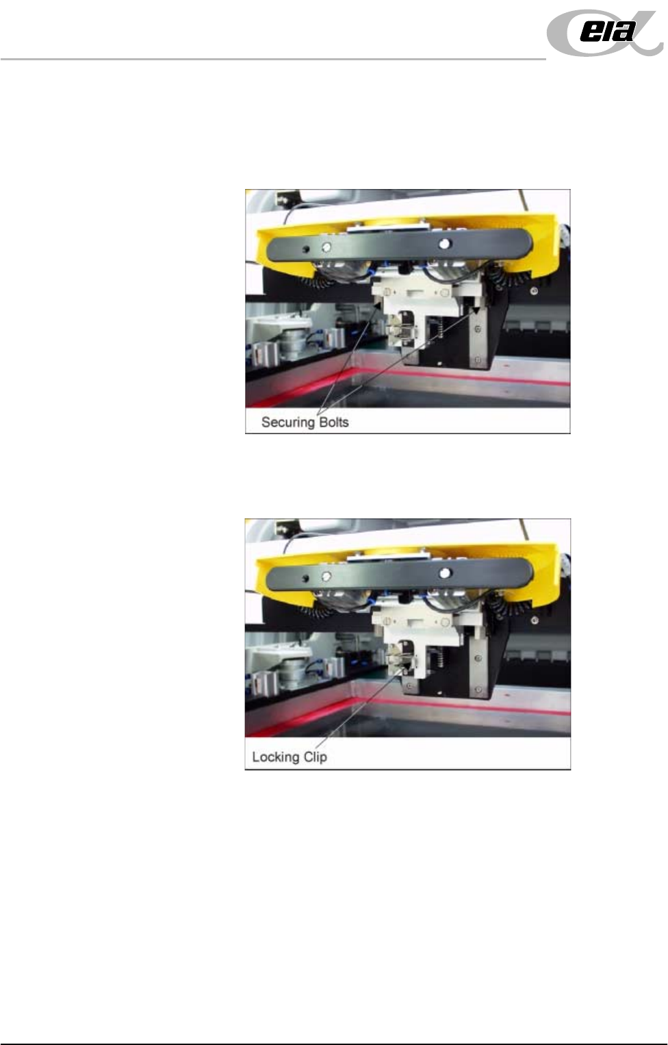
2. Fit the pressure mechanism part of the ProFlow unit to the ProFlow printhead
mechanism bearing block by means of the two securing bolts. Tighten using
a 5mm Allen key.
NOTE
Unit shown in unlatched position to identify bolts..
3. Ensure that the locking clip on the pressure mechanism is pressed over to the
right and clicks into place, as shown in the figure below. This ensures that
the locking clip is in the correct position to secure the transfer head.