P-195-001e.pdf - 第4页
MODEL TCM-3000Z-2 0108-001 2 USING YOUR EXPLODED ILLUSTRATION 1. Subject This Exploded Illustration can be used only for the machines whose rating plates have manufac- turing Nos. that end with - . 2. Inquiring (1) For i…
MODEL TCM-3000Z-2
0108-001
1
1.
2.
(1)
Key No.
(2) Q’ty 1
1
3.
(1)
c d (Serial No. )
e (Fig.No.) fKey No. g (PART No.)
h (PART NAME) i (Q’ty)
( )
(2) Work Corresponding
(3) VARIANT
4.
(1)
(2)
Q’ty
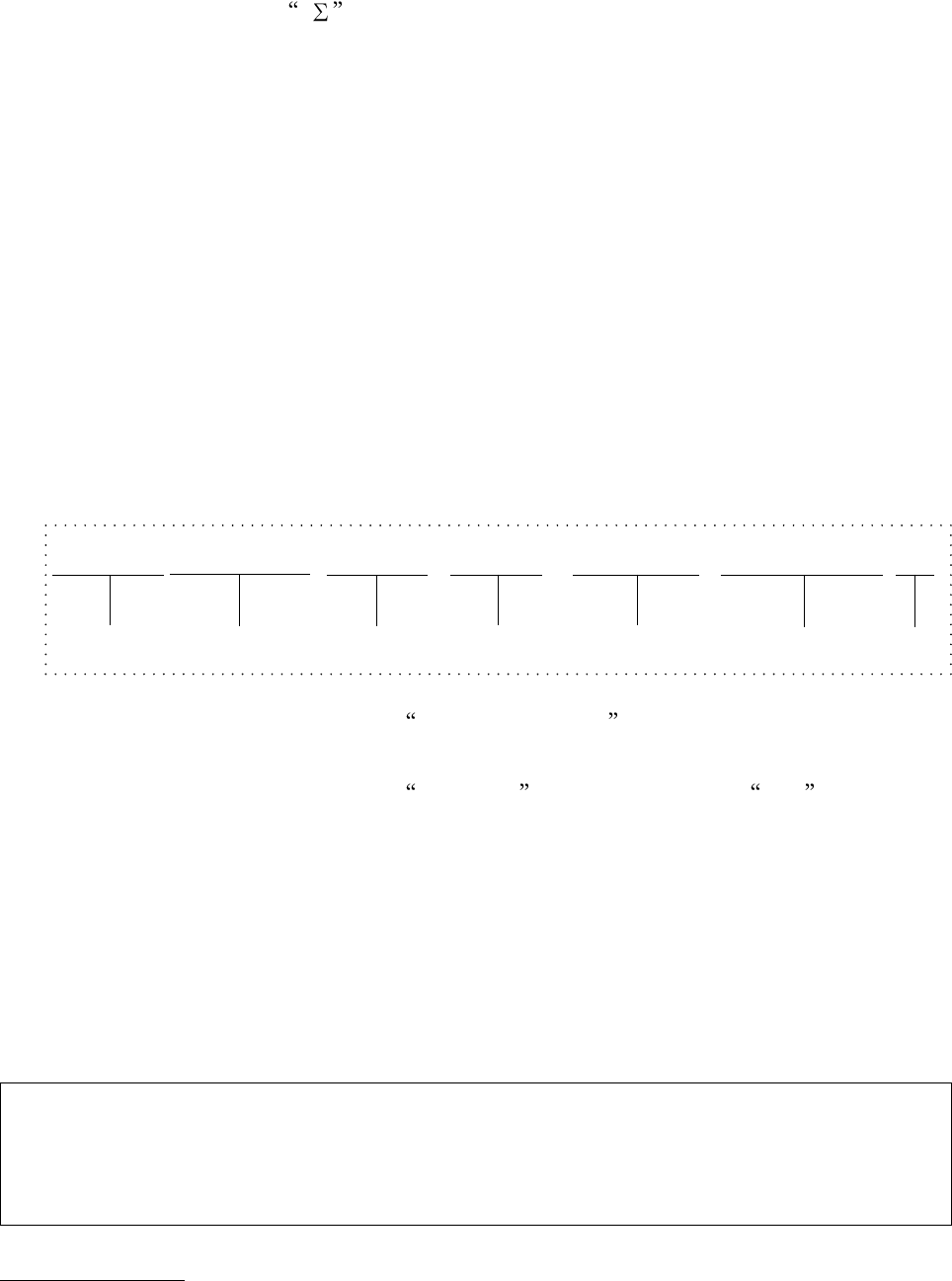
123456S 7890-Σ
Fig. 7-1 Key No.48 630 001 9117 SPRING,TENSION 4TCM-3000Z-2
Model Type Serial No. Fig. No. Key No. PART No.
PART NAME
MODEL TCM-3000Z-2
0108-001
2
USING YOUR EXPLODED ILLUSTRATION
1. Subject
This Exploded Illustration can be used only for the machines whose rating plates have manufac-
turing Nos. that end with - .
2. Inquiring
(1) For identification of each part, numbers are placed on illustration pages. These numbers
(Key No.) again appear in the far left column of the part table joined up with the illustration.
(2) The number shown in the Q’ty column of the part table represents the quantity of certain
part used in the equipment. In case of unit assembly, however, the number represents the
quantity of certain part contained in single unit.
3. Parts Ordering
(1) When ordering parts, be sure to inform us of the following details:
cModel Type of the equipment dSerial No.(See the name plate of the equipment.)
eFig. No. fKey No. gPART No. hPART NAME iQuantity
[Example]
(2) As for the parts with the indication Work Corresponding , refer to the Work Corresponding
Table (List of Vacuum Nozzle Types) in the Instruction Manual.
(3) As for the parts with the indication VARIANT , follow the instrucion in Note in the
illustration.
4. Miscellaneous
(1) The Exploded Illustration is subject to change without prior notice.
(2) All rights reserved. No part of this work covered by the copyrights hereon may be
reproduced or copied without written permission of the publisher.
Some of the parts shown in the Exploded Illustration could fall into the scope of your
government’s regulations on strategic products. In that case, anybody who intend to
export the product should acquire due authorization.
Fig. 7-1 630 001 9117 SPRING, TENSION 4
TCM-3000Z-2
Model Type Serial No. Fig. No. Key No. PART No. PART NAME
Q’ty
Key No.48
123456S 7890-Σ
MODEL TCM-3000Z-2
0108-001
3
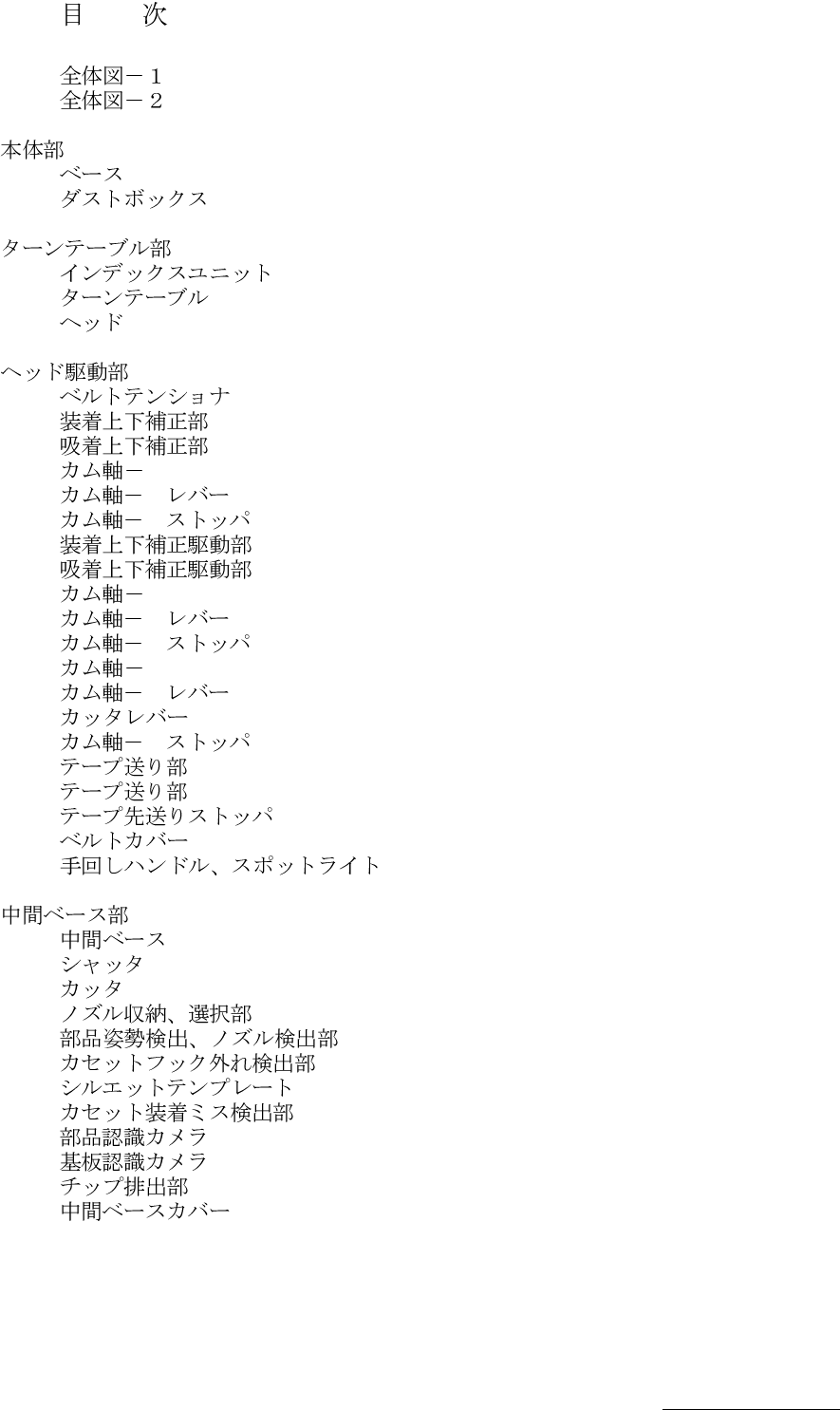
CONT-1
CONTENTS
UNIT LAYOUT -1
UNIT LAYOUT -2
Fig. 1
MAIN BODY SECTION
Fig. 1-1
Base
Fig. 1-2
Dust Box
Fig. 2
TURNTABLE SECTION
Fig. 2-1
Indexing Drive Unit
Fig. 2-2
Turntable
Fig. 2-3
ASSY Head Assy
Fig. 3
HEAD DRIVING SECTION
Fig. 3-1
Belt Tensioner
Fig. 3-2
Placement Level Adjuster
Fig. 3-3
Pick-up Level Adjuster
Fig. 3-4
1 Cam Shaft-1
Fig. 3-5
1 Cam Shaft-1 Lever
Fig. 3-6
1 Cam Shaft-1 Stopper
Fig. 3-7
Placement Level Adjuster Driver
Fig. 3-8
Pick-up Level Adjuster Driver
Fig. 3-9
2 Cam Shaft-2
Fig. 3-10
2 Cam Shaft-2 Lever
Fig. 3-11
2 Cam Shaft-2 Stopper
Fig. 3-12
3 Cam Shaft-3
Fig. 3-13
3 Cam Shaft-3 Lever
Fig. 3-14
Cutter Lever
Fig. 3-15
3 Cam Shaft-3 Stopper
Fig. 3-16
1 Tape Feed Section-1
Fig. 3-17
2 Tape Feed Section-2
Fig. 3-18
Tape Pre-Feeder Stopper
Fig. 3-19
Belt Cover
Fig. 3-20
Hand Wheel, Spotlight
Fig. 4
MIDDLE BASE SECTION
Fig. 4-1
Middle Base
Fig. 4-2
Shutter
Fig. 4-3
Cutter
Fig. 4-4
Nozzle Storager, Nozzle Level Selector
Fig. 4-5
Component Posture Detector, Nozzle Detector
Fig. 4-6
Disengaged Feeder Hook Detector
Fig. 4-7
Silhouette Template
Fig. 4-8
Feeder Miss-setting Detector
Fig. 4-9
Recognition Camera
Fig. 4-10
P.E.C. Camera
Fig. 4-11
Component Discharger
Fig. 4-12
Middle Base Cover