ZFBT-6GW+_dashboard.pdf - 第2页
Notes A. Performance and quality attributes and conditions not expressly stated in this specification document are intended to be excluded and do not form a part of this specification document. B. Electrical specifications …
Notes
A.
Performance and quality attributes and conditions not expressly stated in this specification document are intended to be excluded and do not form a part of this specification document.
B.
Electrical specifications and performance data contained in this specification document are based on Mini-Circuit’s applicable established test performance criteria and measurement instructions.
C.
The parts covered by this specification document are subject to Mini-Circuits standard limited warranty and terms and conditions (collectively, “Standard Terms”); Purchasers of this part are entitled
to the rights and benefits contained therein. For a full statement of the Standard Terms and the exclusive rights and remedies thereunder, please visit Mini-Circuits’ website at www.minicircuits.com/MCLStore/terms.jsp
Mini-Circuits
®
www.minicircuits.com P.O. Box 350166, Brooklyn, NY 11235-0003 (718) 934-4500 sales@minicircuits.com
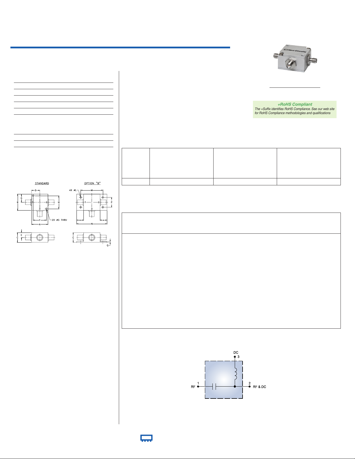
50Ω Wideband 0.1 to 6000 MHz
Bias-Tee
Coaxial
Maximum Ratings
Coaxial Connections
RF 1 (SMA female)
RF&DC 2 (SMA male)
DC 3 (SMA female)
Electrical Schematic
Operating Temperature -55°C to 100°C
Storage Temperature -55°C to 100°C
RF Power 30 dBm max.
Voltage at DC port 30 V max.
Input Current 500 mA
DC resistance from DC to RF&DC port 4.5 ohm typ.
Features
• wideband, 0.1 to 6000 MHz
• low insertion loss, 0.6 dB typ.
• good isolation, 40 dB typ.
Applications
• biasing amplifiers
• biasing of laser diodes
• biasing of active antennas
• DC return
• DC blocking
• test accessory
ZFBT-6GW+
Outline Dimensions ( )
inch
mm
Outline Drawing
CASE STYLE: K18
Connectors Model
SMA ZFBT-6GW+
BRACKET (OPTION “B”)
A
B
C
D
E
F
G
H
1
.25
1
.25
.
75
.
63
.
38
1
.00
.
125
1
.000
31.75 31.75 19.05 16.00 9.65 25.40 3.18 25.40
J
K
L
M
N
P
Q
w
t
-
-
-
-
.
125
1
.688
2
.18
.
75
.
07
g
rams
-- -- 3.18 42.88 55.37 19.05 1.78
7
0.0
REV. C
M151107
ZFBT-6GW+
DJ/RS/CP/AM
151007
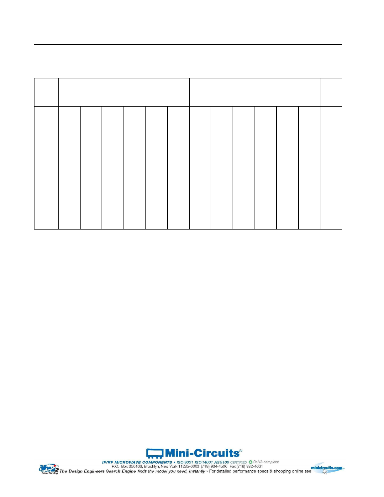
Bias-Tee Electrical Specifications
Typical Performance Data
FREQUENCY
(MHz)
INSERTION LOSS*
(dB)
ISOLATION* (dB)
(RF port to DC port)
(RF&DC port to DC port)
VSWR**
(:1)
L M U L M U L M U
f
L
f
U
Ty p. Max. Ty p. Max. Ty p. Max. Ty p. Min. Typ. Min. Ty p. Min. Ty p. Max. Ty p. Max. Typ. Max.
0.1 6000 0.15 0.8 0.6 1.4 1.0 2.2 25 15 40 20 30 17 1.06 1.6 1.13 1.3 1.13 1.5
L= low range (f
L
to 10 f
L
) M= mid range (10 f
L
to f
U
/2) U= upper range (f
U
/2 to f
U
)
* Insertion Loss 1 dB Max. and isolation 7dB Min. 0.1 to 0.3 MHz.
Insertion Loss and Isolation are guaranteed up to 20 dBm-RF power and 200mA DC current.
**VSWR measured with open and short at DC port.
Freq.
(MHz)
Pin
(dBm)
INSERTION LOSS (dB)
with Current
ISOLATION (dB)
(Pin= -10dBm) with current
VSWR
(:1)
0mA 20mA 50mA 100mA 150mA 200mA 10mA 20mA 50mA 100mA 150mA 200mA
0.10 19.80 0.17 0.17 0.16 0.17 0.20 0.24 19.46 19.04 17.83 14.58 12.66 11.75 1.16
0.27 19.80 0.13 0.13 0.13 0.14 0.14 0.15 25.86 25.53 24.52 21.43 19.31 18.16 1.07
0.53 19.80 0.12 0.12 0.12 0.11 0.11 0.11 29.17 28.98 28.36 26.18 24.40 23.37 1.04
1.06 19.80 0.13 0.13 0.12 0.11 0.12 0.12 30.81 30.74 30.56 29.62 28.62 27.92 1.02
10.00 18.50 0.16 0.17 0.17 0.16 0.16 0.16 30.06 30.07 30.07 30.20 30.38 30.56 1.04
114.75 19.50 0.22 0.25 0.24 0.22 0.22 0.22 34.45 34.49 34.27 33.99 33.83 33.59 1.07
324.25 19.70 0.50 0.55 0.53 0.52 0.53 0.56 44.65 44.61 44.25 43.90 43.91 43.34 1.06
743.25 18.70 0.28 0.31 0.30 0.29 0.29 0.29 51.19 50.50 50.16 50.65 51.69 52.47 1.06
952.75 18.20 0.31 0.33 0.33 0.31 0.32 0.33 40.75 40.80 40.97 40.97 40.93 40.95 1.11
1581.25 18.00 0.46 0.48 0.47 0.46 0.48 0.49 42.58 42.59 43.94 43.77 44.36 44.17 1.13
2000.25 17.10 0.46 0.48 0.47 0.46 0.46 0.47 45.46 45.57 45.73 45.48 46.14 45.28 1.12
2524.00 14.40 0.40 0.42 0.41 0.42 0.43 0.44 53.15 53.72 52.19 53.17 52.67 53.67 1.12
3047.75 14.20 0.45 0.48 0.47 0.46 0.46 0.49 52.46 52.25 51.55 51.33 51.46 50.99 1.09
3676.25 15.10 0.73 0.74 0.75 0.75 0.75 0.75 46.32 47.19 46.36 45.53 46.19 45.65 1.07
4200.00 17.90 1.04 1.07 1.07 1.06 1.05 1.06 28.42 28.36 28.24 28.14 28.01 27.92 1.09
4502.50 -0.60 1.17 1.19 1.18 1.19 1.17 1.16 28.15 28.10 28.05 27.96 27.84 27.87 1.14
4802.00 -0.70 1.26 1.26 1.27 1.25 1.22 1.20 37.95 38.01 38.19 37.93 37.58 37.51 1.12
5251.75 -1.10 1.19 1.17 1.16 1.13 1.11 1.09 49.68 51.04 49.12 49.37 49.13 48.19 1.11
5550.75 -2.00 1.65 1.63 1.60 1.56 1.54 1.51 38.44 38.56 38.36 38.07 37.85 38.19 1.10
6000.00 -2.40 1.70 1.71 1.65 1.59 1.54 1.50 34.37 34.36 34.23 34.40 34.49 34.48 1.12
Permanent damage may occur if any of these limits are exceeded.
+RoHS Compliant
The +Suffix identifies RoHS Compliance. See our web site
for RoHS Compliance methodologies and qualifications
Generic photo used for illustration purposes only
Notes
A.
Performance and quality attributes and conditions not expressly stated in this specification document are intended to be excluded and do not form a part of this specification document.
B.
Electrical specifications and performance data contained in this specification document are based on Mini-Circuit’s applicable established test performance criteria and measurement instructions.
C.
The parts covered by this specification document are subject to Mini-Circuits standard limited warranty and terms and conditions (collectively, “Standard Terms”); Purchasers of this part are entitled
to the rights and benefits contained therein. For a full statement of the Standard Terms and the exclusive rights and remedies thereunder, please visit Mini-Circuits’ website at www.minicircuits.com/MCLStore/terms.jsp
Mini-Circuits
®
www.minicircuits.com P.O. Box 350166, Brooklyn, NY 11235-0003 (718) 934-4500 sales@minicircuits.com
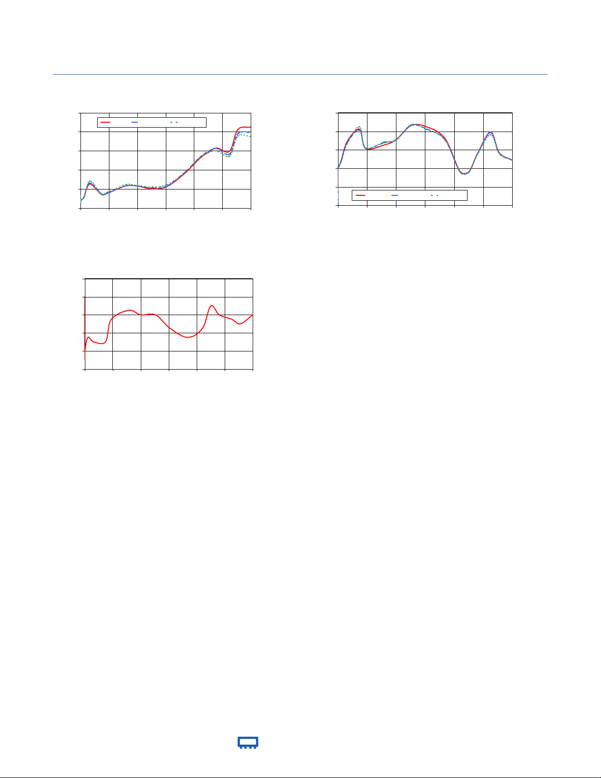
Performance Charts
ZFBT-6GW+
INSERTION LOSS WITH CURRENT
0.0
0.4
0.8
1.2
1.6
2.0
0 1000 2000 3000 4000 5000 6000
FREQUENCY (MHz)
INSERTION LOSS (dB)
0mA 100mA 200mA
ZFBT-6GW+
ISOLATION WITH CURRENT
10
20
30
40
50
60
0 1000 2000 3000 4000 5000 6000
FREQUENCY (MHz)
ISOLATION (dB)
10mA 100mA 200mA
ZFBT-6GW+
VSWR
1.00
1.04
1.08
1.12
1.16
1.20
0 1000 2000 3000 4000 5000 6000
FREQUENCY (MHz)
VSWR
ZFBT-6GW+
Bias Tee, Coaxial ZFBT-6GW+
Typical Performance Data
(MHz)
(:1)
0.10
0.17
0.17
0.16
0.17
0.20
0.24
19.46
19.04
17.83
14.58
12.66
11.75
1.16
0.27
0.13
0.13
0.13
0.14
0.14
0.15
25.86
25.53
24.52
21.43
19.31
18.16
1.07
0.53
0.12
0.12
0.12
0.11
0.11
0.11
29.17
28.98
28.36
26.18
24.40
23.37
1.04
1.06
0.13
0.13
0.12
0.11
0.12
0.12
30.81
30.74
30.56
29.62
28.62
27.92
1.02
10.00
0.16
0.17
0.17
0.16
0.16
0.16
30.06
30.07
30.07
30.20
30.38
30.56
1.04
114.75
0.22
0.25
0.24
0.22
0.22
0.22
34.45
34.49
34.27
33.99
33.83
33.59
1.07
324.25
0.50
0.55
0.53
0.52
0.53
0.56
44.65
44.61
44.25
43.90
43.91
43.34
1.06
743.25
0.28
0.31
0.30
0.29
0.29
0.29
51.19
50.50
50.16
50.65
51.69
52.47
1.06
952.75
0.31
0.33
0.33
0.31
0.32
0.33
40.75
40.80
40.97
40.97
40.93
40.95
1.11
1581.25
0.46
0.48
0.47
0.46
0.48
0.49
42.58
42.59
43.94
43.77
44.36
44.17
1.13
2000.25
0.46
0.48
0.47
0.46
0.46
0.47
45.46
45.57
45.73
45.48
46.14
45.28
1.12
2524.00
0.40
0.42
0.41
0.42
0.43
0.44
53.15
53.72
52.19
53.17
52.67
53.67
1.12
3047.75
0.45
0.48
0.47
0.46
0.46
0.49
52.46
52.25
51.55
51.33
51.46
50.99
1.09
3676.25
0.73
0.74
0.75
0.75
0.75
0.75
46.32
47.19
46.36
45.53
46.19
45.65
1.07
4200.00
1.04
1.07
1.07
1.06
1.05
1.06
28.42
28.36
28.24
28.14
28.01
27.92
1.09
4502.50
1.17
1.19
1.18
1.19
1.17
1.16
28.15
28.10
28.05
27.96
27.84
27.87
1.14
4802.00
1.26
1.26
1.27
1.25
1.22
1.20
37.95
38.01
38.19
37.93
37.58
37.51
1.12
5251.75
1.19
1.17
1.16
1.13
1.11
1.09
49.68
51.04
49.12
49.37
49.13
48.19
1.11
5550.75
1.65
1.63
1.60
1.56
1.54
1.51
38.44
38.56
38.36
38.07
37.85
38.19
1.10
6000.00
1.70
1.71
1.65
1.59
1.54
1.50
34.37
34.36
34.23
34.40
34.49
34.48
1.12
150mA 200mA
INSERTION LOSS with current
(RF Port to RF&DC Port)
FREQ.
(dB)
0mA 20mA 50mA 100mA
VSWR
ISOLATION with current
(RF Port to DC Port, RF&DC Port to DC Port)
(dB)
10mA 20mA 50mA 100mA 150mA 200mA
REV. X1
ZFBT-6GW+
070717
Page 1 of 1