e6d-c_ds_e_5_2_csm497.pdf - 第3页
E6D-C 3 I/O Circuit Diagrams Model/Output Circ uits Output mode Connection E6D-CWZ1E +5 V 0 V GND Output Brown (Black: phase A, White: phase B, Orange: phase Z) Blue Shield Black, white, orange 30 Ω 1 k Ω TTL 7407 E6D ma…
E6D-C
2
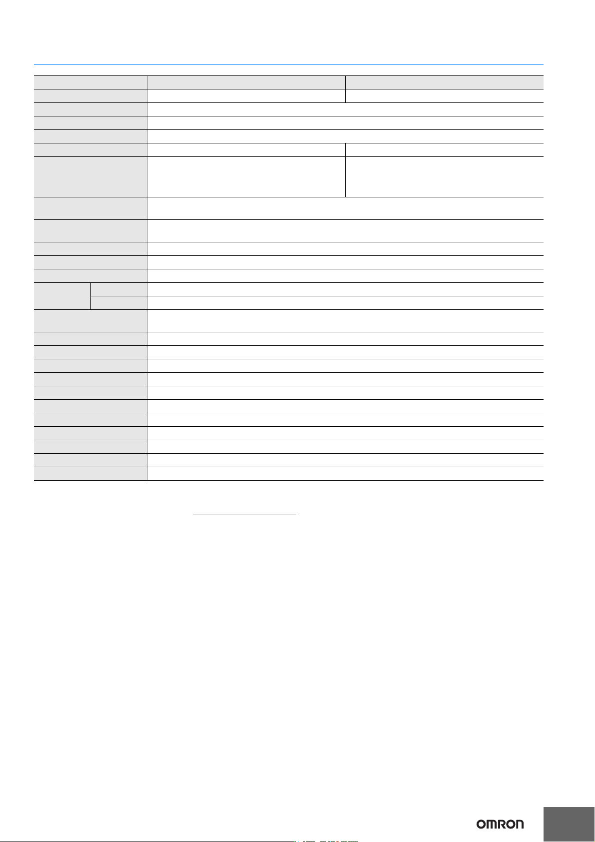
Ratings and Specifications
*1. An inrush current of approximately 2 A will flow for approximately 50 μs when the power is turned ON.
*2. The maximum electrical response speed is determined by the resolution and maximum response frequency as follows:
This means that the Rotary Encoder will not operate electrically if its speed exceeds the maximum electrical response speed.
*3. No protection is provided against water or oil.
Item Model E6D-CWZ1E E6D-CWZ2C
Power supply voltage 5 VDC ±5%, ripple (p-p): 5% max. 12 VDC ±10%, ripple (p-p): 5% max.
Current consumption*1 150 mA max.
Resolution (pulses/rotation) 1,000, 2,000, 3,600, 5,000, 6,000
Output phases Phases A, B, and Z
Output configuration Voltage output Open-collector output
Output capacity
Output resistance: 1 kΩ
Sink current: 35 mA max.
Residual voltage: 0.7 V max. (at sink current of 10 mA)
Applied voltage: 30 VDC max.
Sink current: 35 mA max.
Residual voltage: 1 V max. (at sink current of 35 mA)
Residual voltage: 0.7 V max. (at sink current of 10 mA)
Maximum response fre-
quency*2
200 kHz
Phase difference between
outputs
90°±25° between A and B (1/4 T ± 0.07 T)
Rise and fall times of output 1 μs max.
Starting torque 9.8 mN·m max.
Moment of inertia 3 × 10
−6
kg·m
2
max.
Shaft loading
Radial 50 N (20 N to maintain accuracy)
Thrust 30 N (10 N to maintain accuracy)
Maximum permissible
speed
12,000 r/min
Ambient temperature range Operating: −10 to 70°C (with no icing), Storage: −25 to 80°C (with no icing)
Ambient humidity range Operating/Storage: 35% to 85% (with no condensation)
Insulation resistance Excluded because of capacitor ground.
Dielectric strength Excluded because of capacitor ground.
Vibration resistance Destruction: 10 to 55 Hz, 1.5-mm double amplitude for 2 hours each in X, Y, and Z directions
Shock resistance Destruction: 500 m/s
2
3 times each in X, Y, and Z directions
Degree of protection*3 IEC 60529 IP50
Connection method Pre-wired Models (Standard cable length: 0.5 m)
Material Case: Zinc alloy, Main unit: Aluminum, Shaft: SUS303, Mounting Bracket: Galvanized iron
Weight (packed state) Approx. 280 g
Accessories E69-C06B Coupling, E69-2 Servo Mounting Bracket, Hexagonal wrench, Instruction manual
Maximum electrical response speed (rpm) =
Maximum response frequency
× 60
Resolution
E6D-C
3
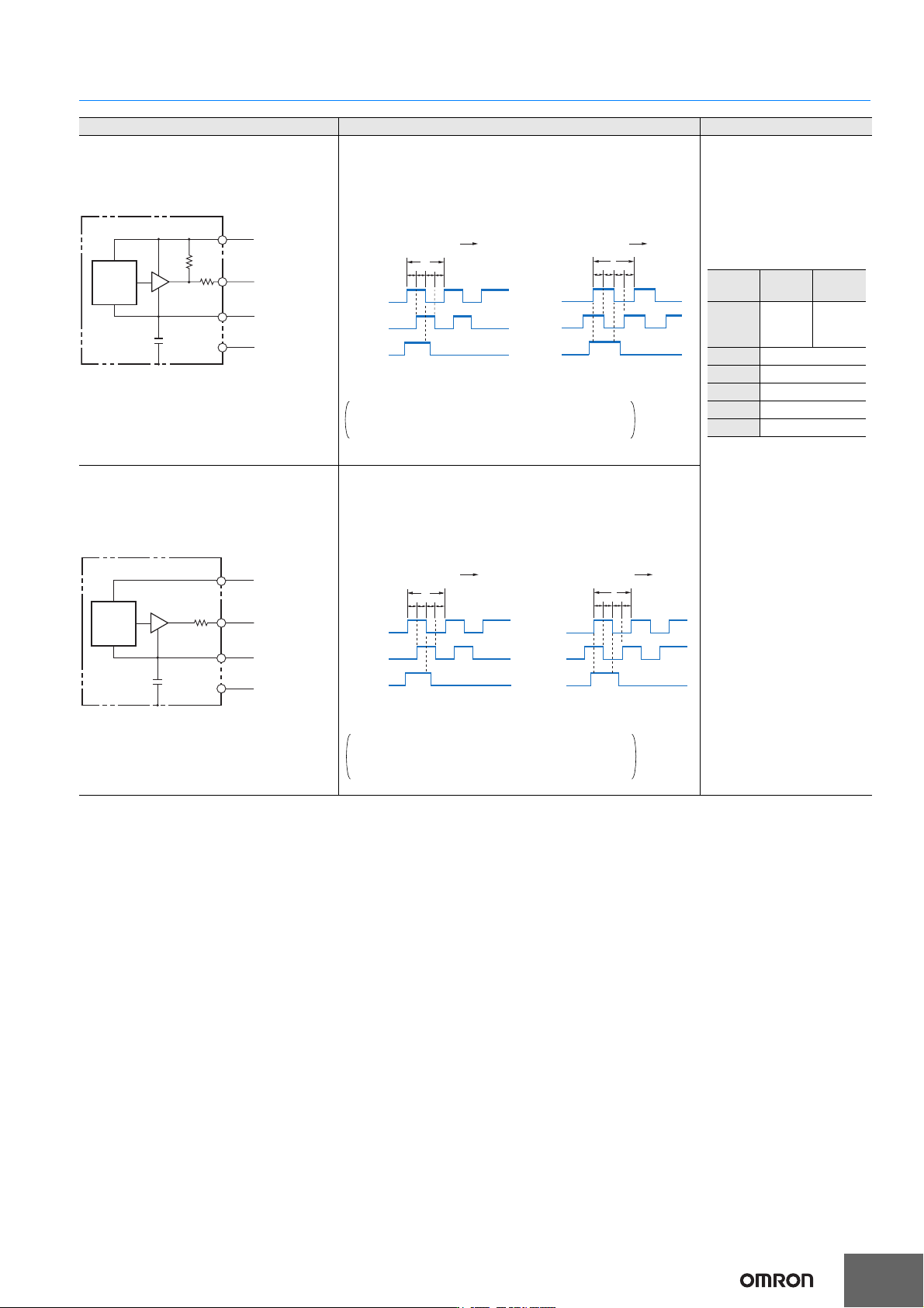
I/O Circuit Diagrams
Model/Output Circuits Output mode Connection
E6D-CWZ1E
+5 V
0 V
GND
Output
Brown
(Black: phase A,
White: phase B,
Orange: phase Z)
Blue
Shield
Black, white,
orange
30 Ω
1 kΩ
TTL
7407
E6D
main
circuit
Phase A
Phase B
Phase Z
H
L
H
L
H
L
(360°)
T
CW
t
1,
t
2,
t
3,
t
4
=90°±25°
(1/4T±7/100T)
t1
Phase A
Phase B
Phase Z
H
L
H
L
H
L
CCW
t
4t3t2
t1, t2, t3, t4=90°±25°
(1/4T±7/100T)
(360°)
T
t
1 t4t3t2
E6D-CWZ1E Voltage output
Direction of rotation: CW
(as viewed from end of shaft)
Direction of rotation: CCW
(as viewed from end of shaft)
Note: Phase A is 1/4 T
±
7/100 T faster
than phase B.
Phase Z is synced with phase A.
Note: Phase A is 1/4 T
±
7/100 T
slower than phase B.
Phase Z is synced with phase A.
“H” and “L” in the diagrams are the output voltage
levels of phases A, B, and Z.
Note: 1. The shielded cable outer
core (shield) is not
connected to the inner
area or to the case.
2. The phase A, phase B,
and phase Z circuits are
all identical.
3. Normally, connect GND
externally to 0 V or to
ground.
Peripheral Device Precautions
(1) When connecting to a coun-
ter, use the 12-VDC Model
E6D-CWZ2C.
(2) For counters with voltage
inputs, insert pull-up resis-
tance of 4.7 Ω and 1/4 W.
Model
Color
E6D-CWZ1E E6D-CWZ2C
Brown
Power
supply
+5 V
Power
supply
+12 V
Black Phase A output
White Phase B output
Orange Phase Z output
Blue 0 V (common)
Shield GND
E6D-CWZ2C
E6D
main
circuit
Output
Brown
(Black: phase A,
White: phase B,
Orange: phase Z)
Blue
Shield
Black, white,
orange
30 Ω
TTL
7407
+12 V
GND
0 V
CW
t
3t2
t1
(360°)
T
t
4
t
1,
t
2,
t
3,
t
4
=90°±25°
(1/4T±7/100T)
CCW
Phase A
Phase B
Phase Z
ON
OFF
ON
OFF
ON
OFF
t3t2
t1
(360°)
T
t
4
t
1,
t
2,
t
3,
t
4
=90°±25°
(1/4T±7/100T)
Phase A
Phase B
Phase Z
ON
OFF
ON
OFF
ON
OFF
E6D-CWZ2C Open-collector output
Direction of rotation: CW
(as viewed from end of shaft)
Direction of rotation: CCW
(as viewed from end of shaft)
The ONs in the above timing chart mean that the
output transistor is ON and the OFFs mean that the
output transistor is OFF.
Note: Phase A is 1/4 T
±
7/100 T faster
than phase B.
Phase Z is synced with phase A.
Note: Phase A is 1/4 T
±
7/100 T
slower than phase B.
Phase Z is synced with phase A.
E6D-C
4
Safety Precautions
Refer to Warranty and Limitations of Liability.
This product is not designed or rated for ensuring
safety of persons either directly or indirectly.
Do not use it for such purposes.
Do not use the Encoder under ambient conditions that exceed the
ratings.
z Wiring
Spurious pulses may be generated when power is turned ON and
OFF. Wait at least 0.1 s after turning ON the power to the Encoder
before using the connected device, and stop using the connected
device at least 0.1 s before turning OFF the power to the Encoder.
Also, turn ON the power to the load only after turning ON the power
to the Encoder.
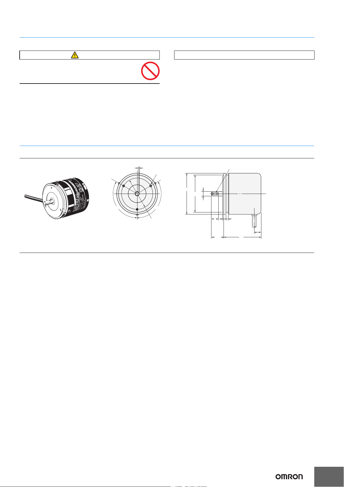
(Unit: mm)
Dimensions Tolerance class IT16 applies to dimensions in this datasheet unless otherwise specified.
Encoder
Accessories (Order Separately)
Refer to Accessories for details.
WARNING
Precautions for Correct Use
E6D
*
9
5016.5
31.5
39
120˚120˚
42±
0.1
dia.
0.5
55 dia.
50
+0
-0.04
dia.
Three, M3 × 0.5
screws
(Screw depth: 6 mm)
Cut face D on shaft
*5-dia. vinyl-insulated
shielded round cable with
5 conductions
(Conductor cross section:
0.18 mm
2
, Insulator
diameter: 1.1 mm),
Standard length: 500 mm
An E69-C06B Coupling and
E69-2 Servo Mounting Bracket
are provided with the product.
6
-
0.004
-0.016
dia.