ES40-60-AR10-A.pdf - 第3页
0.4 MPa Setting The setting specification is 0.4 MPa. When a pressure gauge is included, the display will show a range from 0 to 1.0 MPa. Applicable Model Model AR10 Port size M5 AR 10 X406 M5 A 0.4 MPa setting w q * 2 O…
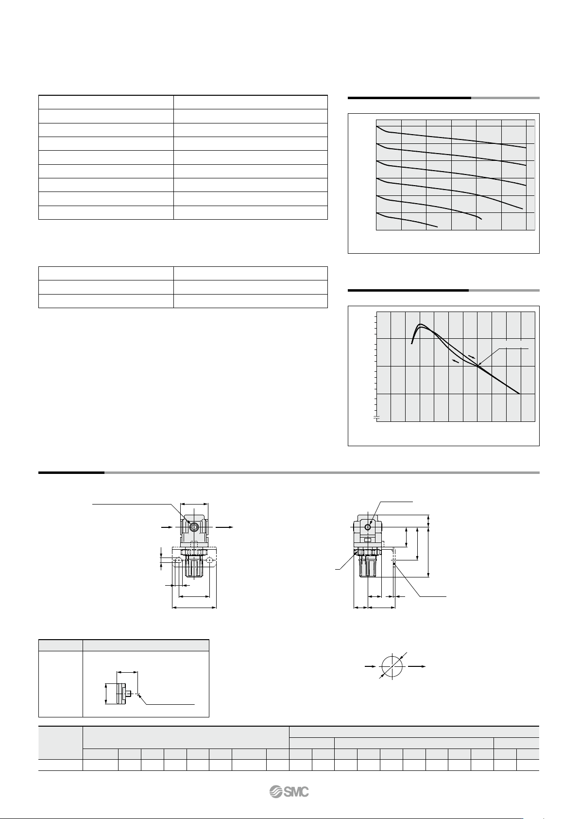
Port size M5 x 0.8
Pressure gauge port size
*
1
1/16
Fluid Air
Ambient and fluid temperature –5 to 60°C (with no freezing)
Proof pressure 1.5 MPa
Maximum operating pressure 1.0 MPa
Set pressure range 0.05 to 0.7 MPa
Construction Relieving type
Weight 0.06 kg
Standard Specifications
Bracket assembly
*
1
AR12P-270AS
Set nut AR12P-260S
Round type pressure gauge
*
2
G27-10-R1
Options/Part No.
*1 Assembly of a bracket and set nuts
*2 1.0 MPa pressure gauge
*1 Use a bushing (part no.: 131368) when connecting the R1/8 pressure gauge to the Rc1/16.
0.6
0.5
0.4
0.3
0.2
0.1
0
0 25 50 75 100 125 150
Outlet pressure [MPa]
Flow rate [L/min (ANR)]
Flow Rate Characteristics (Representative values)
AR10-A
M5
Condition: Inlet pressure of 0.7 MPa
0
0.15
0.2
0.25
0.3
0 0.1 0.2 0.3 0.4 0.5 0.6 0.7 0.8 0.9 1
Outlet pressure [MPa]
Inlet pressure [MPa]
Set point
Pressure Characteristics (Representative values)
AR10-A
Conditions: Inlet pressure of 0.7 MPa,
Outlet pressure of 0.2 MPa,
Flow rate 20 L/min (ANR)
Dimensions
AR10-A
M
UD
J
F
2 x P1
(Port size)
CB
Q
V
T
N
S
R
A2 x P2
(Pressure gauge port size)
IN
OUT
Bracket
(Option)
IN
OUT
W
Panel mounting dimensions
Plate thickness
AR10-A: MAX.3.5
*1 The dimension of B is the length when the filter regulator knob is unlocked.
Option Round type pressure gauge
Dimensions
Center of piping
H
J
Model
Standard specifications
Optional specifications
Round type pressure gauge
Bracket mount
Panel mount
P1 P2 A B
*
1
C D F J
H J
M N Q R S T U V W
AR10-A
M5 x 0.8 1/16 25 47.4 11 12.5 M18 x 1 12.5
ø
26 26 25 28 30 4.5 6.5 40 2 18 18.5
14
Regulator AR10-A Series
A
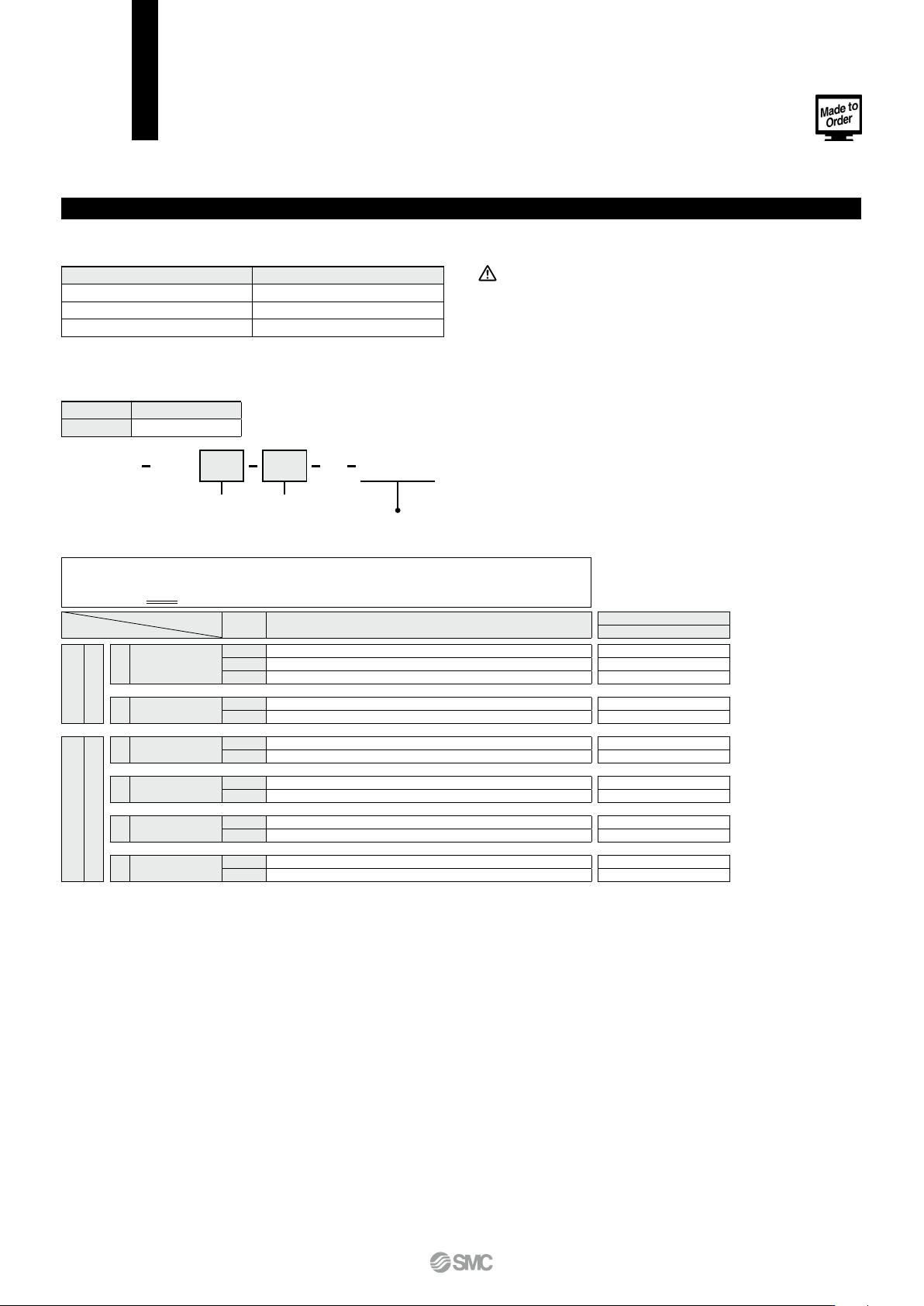
0.4 MPa Setting
The setting specification is 0.4 MPa. When a pressure gauge is included, the display will show a range from 0 to 1.0 MPa.
Applicable Model
Model
AR10
Port size M5
AR 10 X406M5 A
0.4 MPa setting
wq
*2 Options B, G, H are not assembled and supplied loose at the time of shipment.
*3 Assembly of a bracket and set nuts.
*4 A 1.0 MPa pressure gauge will be fitted.
*5 This product is for overseas use only according to the new Measurement Act. (The SI unit type is provided for use in Japan.)
*1 Pressure can be set higher than the specification pressure in some cases, but use
pressure within the specification range.
Symbol Description
Body size
10
NNq
a Mounting
Nil
Without mounting option
Option
*
2
B
*
3
With bracket
H
With set nut (for panel mount)
+
b
Pressure gauge
*
4
Nil
Without pressure gauge
G
Round type pressure gauge (without limit indicator)
+
Nw
Semi-standard
c
Exhaust mechanism
Nil
Relieving type
N
Non-relieving type
+
d Flow direction
Nil
Flow direction: Left to right
R
Flow direction: Right to left
+
e Knob
Nil
Downward
Y
Upward
+
f Pressure unit
Nil
Name plate and pressure gauge in SI units: MPa
Z
*
5
Name plate and pressure gauge in imperial units: psi
Caution
• The AR10 comes with a backflow function as a standard feature.
When using the AR10 as with backflow function, backflow may
not occur with the set pressure of 0.15 MPa or less.
Specifications
Made-to-order part no.
-X406
Proof pressure
[MPa] 1.5
Maximum operating pressure [MPa
] 1.0
Set pressure range [MPa]
*
1
0.05 to 0.4
• Select one each for a to f.
• When more than one specification is required, indicate in alphanumeric order.
Example) AR10-M5BG-NR-A-X406
AR10 Regulator
Made to Order
Please contact SMC for detailed dimensions, specifications and lead times.
Option and Semi-standard Symbol Selection
15
A
Selection
Maintenance
Mounting/Adjustment
1. Although exhaust of the residual pressure to the inlet side is
possible when eliminating the inlet pressure, exhaust is not
possible when the set pressure is 0.15 MPa or less.
1. When operating at an inlet pressure lower than the inlet pres-
sure used in the flow rate characteristics graph, the pressure
drop on the outlet side may be greater. Therefore, be sure to
conduct testing using the actual equipment.
For pressure control equipment selection, refer to the “Product
Selection Guide.”
Warning
Caution
1. When using the regulator between a solenoid valve and an ac-
tuator, check the pressure gauge periodically. Sudden pres-
sure fluctuations may shorten the durability of the pressure
gauge. A digital pressure gauge is recommended for such
situation or as deemed necessary.
Warning
1. Set the regulator while verifying the displayed values of the in-
let and outlet pressure gauges. Turning the regulator knob ex-
cessively can cause damage to the internal parts.
2. Do not use tools on the pressure regulator knob as this may
cause damage. It must be operated manually.
Warning
1. Be sure to unlock the knob before adjusting the pressure and lock
it after setting the pressure. Failure to follow this procedure can
cause damage to the knob and the outlet pressure may fluctuate.
• Pull the pressure regulator knob to unlock. (You can visually
verify this with the “orange mark” that appears in the gap.)
• Push the pressure regulator knob to lock. When the knob is not
easily locked, turn it left and right a little and then push it (when
the knob is locked, the “orange mark”, i.e., the gap will disap-
pear).
2. Pulsation will be generated when the difference between the
inlet and the outlet pressure is large. In this case, reduce the
pressure difference between the inlet and the outlet.
Caution
Be sure to read this before handling the products. Refer to the back cover for safety instructions. For F.R.L. units
precautions, refer to the “Handling Precautions for SMC Products” and the “Operation Manual”, https://www.smcworld.com
Specific Product Precautions
16
Regulator AR10-A Series
A