Machine PC LC.pdf
MACHINE PC OVERV IEW Chapter Issue 1, May 17 Technical Reference Manual 6.1 CHAPTER 6 MACHINE P C OVERVI EW Figure 6-1 Machine PC The machine PC hand les all the mac hine functi ons (via CAN Bus and LAN Host Comms), pri …
MACHINE PC
OVERVIEW
Chapter Issue 1, May 17 Technical Reference Manual 6.1
CHAPTER 6 MACHINE PC
OVERVIEW
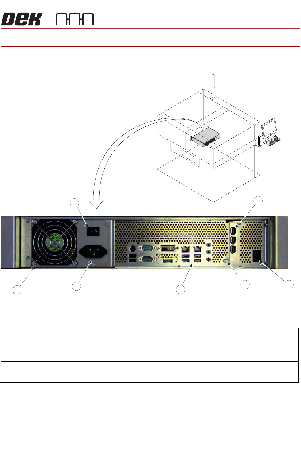
Figure 6-1 Machine PC
The machine PC handles all the machine functions (via CAN Bus and LAN Host
Comms), printer cameras and the MMI.
The PC for the printer is configured using a dual core processor with standard
PCI for the camera system.
Item Description Item Description
1 PCI Interface Card 5 Mains Input Connector
2 Reset Switch 6 Cooling Fan
3 Earth Bonding Connector 7 Mains Power On/Off Switch
4 Peripheral Connector Panel
7
2
PC Enclosure PanelConnector
3
4
6
5
1
MACHINE PC
ELECTRICAL SCHEMATIC
6.2 Technical Reference Manual Chapter Issue 1, May 17
ELECTRICAL SCHEMATIC
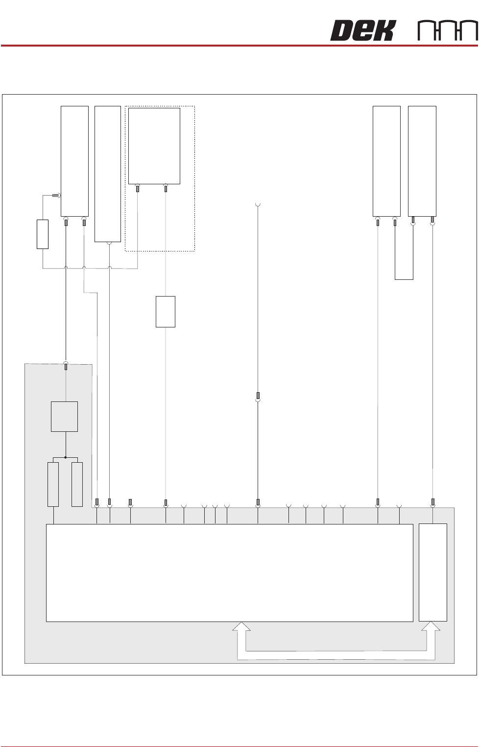
Figure 6-2 Electronic Assembly Machine PC
Rear Service Panel
Host Comms 45 Ethernet PortRJ LAN
613SK
Machine Control Enclosure
M36 16PL
M36 28PL
PC Enclosure
Power Supply Enclosure
M37 30PL
M37 31PL
Digital Camera Module
10 17SK
10 13SK
Motherboard
HDD
FAN
301SK
PSU
Mains In
USB 6
337PL
PCI Bus
LAN Host Comms
302PL
PS2 Mouse
3 07 - Not UsedSK
MMI
Monitor
14 04SK
3 03 -PL (Stinger if fitted)
COM RS1 232
6 Pin Mini Keyboard
USB 2
1USB
3SK57
3 04 - Not UsedSK
- Not Used
Line Out
347SK - Not Used
Line In
Mic In
3 49 - Not UsedSK
3 4 - Not UsedSK 8
USB 3
3 36 - DongleSK
Parallel Port Printer
3 06 - Not UsedSK
305PL
DVI-I
IEEE 1394a (400)
Interface CardPCI
355PL
USB 4
335PL
DVI-I
SVGA
Adaptor
USB 5
356PL
USB Keyboard and Mouse
(rhs c c )over onnector
8PL51
- Not Used
AC/DC
SATA

MACHINE PC
PC ENCLOSURE
Chapter Issue 1, May 17 Technical Reference Manual 6.3
PC ENCLOSURE
Motherboard
System
This motherboard provides the master control of all machine functions, it
houses the Central Processing Unit (CPU) which is an Intel® Pentium® Dual
Core processor G3420 3.2GHz.
The main features of this card are:
• VGA Video Output DVI and HDMI
• 6 USB Ports
• 2 LAN Host Comms
• 6 SATA HDD Controllers
• 2 PCI Bus Interface
• 2 PCIE Interface
• RS232 Interface (COM1)
• RS232 Interface (COM2)
• CMOS RAM with Lithium battery backup (Not Shown)
• 6 Pin Mini Keyboard Connector - Not Used
• 4 DDR3 DIMM Sockets (RAM)
• Line Out Connector - Not Used
• Line In Connector - Not Used
• Mic In - Not Used
CMOS Settings The CMOS settings are password protected to prevent any settings being
changed.
It is highly unlikely that the CMOS settings could be responsible for PC issues
however, if the settings are strongly suspected, contact the CSG Helpdesk.