Nordson_EFD_781S_Installation_Guide.pdf - 第3页
www.nordsonefd.com info@nordsonefd.com +1-401-431-7000 Sales and service of Nordson EFD dispensing systems are available worldwide. 3 781S Series Spray Valve | Installation Guide How the V alve Operates Input air pressur…
www.nordsonefd.com info@nordsonefd.com +1-401-431-7000 Sales and service of Nordson EFD dispensing systems are available worldwide.2
781S Series Spray Valve | Installation Guide
Prior to installing this valve, please read the
associated reservoir and valve controller
operating instructions to become familiar with
the operation of all components of the spray
system.
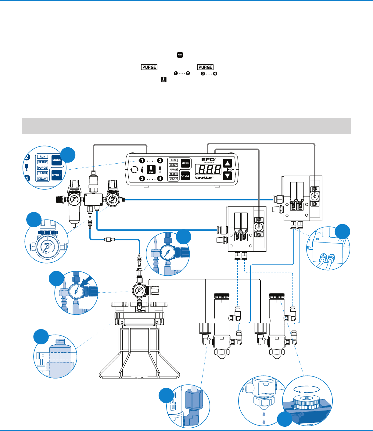
1. Connect the fluid supply line to valve.
2. Connect the fluid supply line to the reservoir.
3. Connect the control air hose and the nozzle
air hose to corresponding outputs on
solenoid block.
4. Fill reservoir by pouring fluid directly into
tank liner or manufacturer’s bottle placed
inside reservoir. Secure cover prior to setting
pressure.
5. Set reservoir pressure to low for thin fluids
and higher for thick fluids.
6. Using the Mode button on the ValveMate
controller, place the controller in the PURGE
mode. In PURGE mode
only, channels and can be
selected independently without nozzle air
pressure.
7. Using the needle stroke control knob on
the 781S valve, set the fluid flow rate to
one or two drops per second. Check the
flow rate by actuating the controller in the
time override mode. Make valve stroke
adjustments when the controller is off.
8. Set the nozzle air pressure on the nozzle to
0.7 bar (10 psi) and actuate the controller.
The valve will produce a fine spray. To
change fluid flow, use the needle stroke
control knob and / or reservoir pressure.
To change nozzle air, use the nozzle air
pressure regulator. Higher pressures will
provide finer spray.
Installation
NOTE: The area of spray coverage is determined by the distance between the spray valve nozzle and the work surface.
Refer to the charts on the back page to determine this distance.
SPRAY VALVE CONTROLLER
8040
EFD 781S
EFD 781S
3
6
5
8
2
4
1
7
Open
Close
www.nordsonefd.com info@nordsonefd.com +1-401-431-7000 Sales and service of Nordson EFD dispensing systems are available worldwide. 3
781S Series Spray Valve | Installation Guide
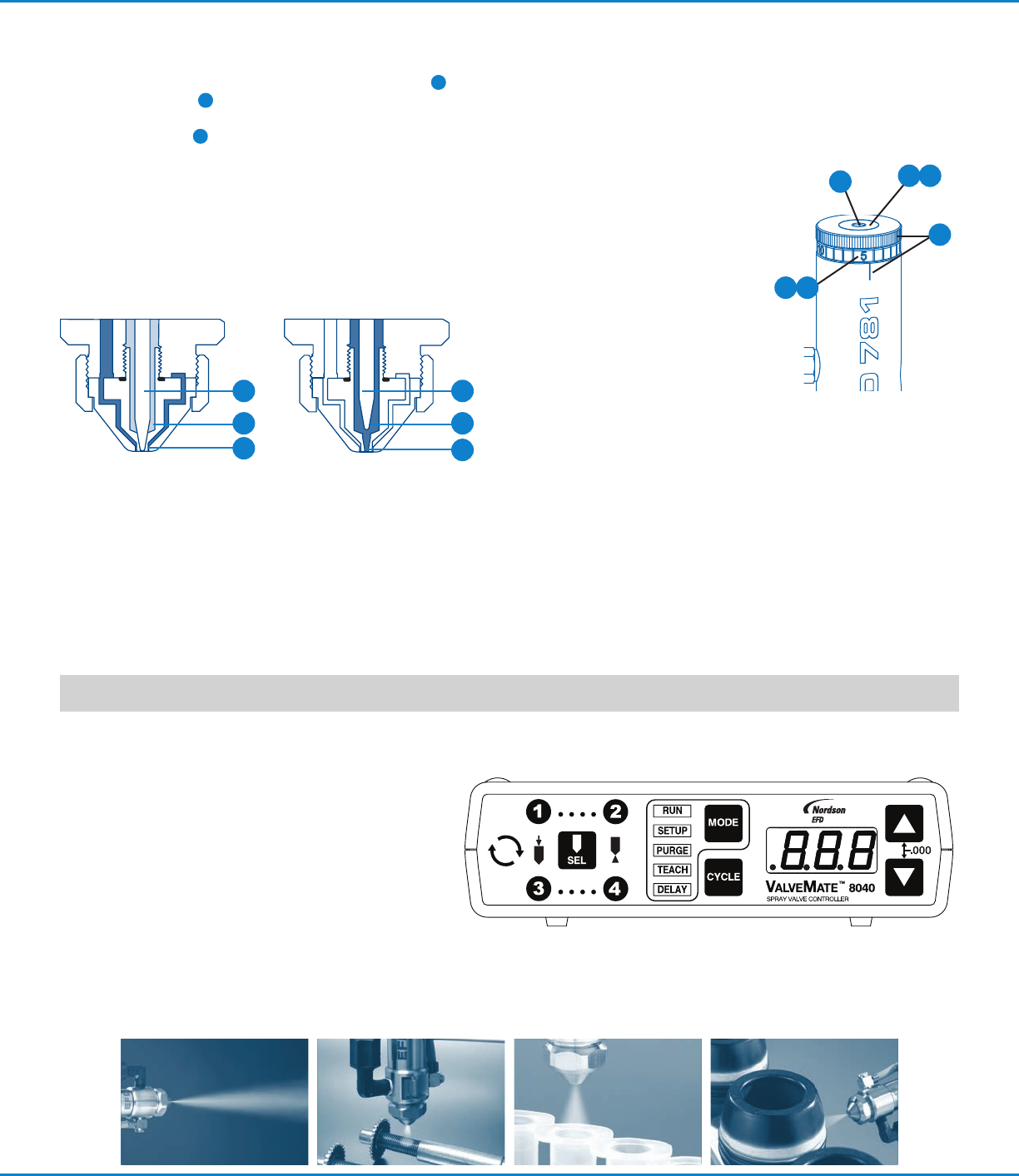
How the Valve Operates
Input air pressure at 4.8 bar (70 psi) retracts the needle
1
from its nozzle seat,
2
allowing liquid to flow from the
nozzle. At the same time, nozzle air is turned on and flows
from the anannulus
3
around the liquid nozzle. This
adjustable nozzle air creates a pressure drop around the
nozzle, causing the liquid to atomize into fine droplets.
The amount sprayed is controlled by the valve open time,
reservoir pressure, and needle stroke*. Area of coverage
is determined by the nozzle size and the distance
between the nozzle and work surface.
ValveMate Concept
The ValveMate
™
8040 provides easy adjustment of
spray valve output for maximum end-user convenience
and efficiency. Valve open time is the primary control of
deposit size. The ValveMate 8040 puts adjustment of
valve open time where it needs to be — near the spray
valve.
External solenoids, combined with a 0–2bar (0–30psi)
nozzle air pressure regulator, provide Low Volume
Low Pressure (LVLP) air to the nozzle, for high transfer
efficiency.
NOTE: Order your single or dual valve solenoid
assemblies separately. Consult Nordson EFD for
recommendations.
The primary control of deposit size is the valve open time.
closed open
1
2
3
1
2
3
Calibration Feature
The stroke control reference ring of each 781S-SS valve
is factory calibrated to the zero position. After cleaning,
disassembly and reassembly, the stroke control zero position
may require recalibration. To do so:
1. Make a note of the current
stroke setting number.
2. Turn the calibration
adjustment knob (inner)
counterclockwise two full
turns.
3. Turn the stroke knob (outer)
clockwise until it stops.
Note reference ring “0”
(zero) location. If “0” is not
positioned above either
reference mark on air cylinder body, rotate outer stroke
knob counterclockwise until “0” is positioned above
preferred referencemark. Select reference mark that is
more clearly visible based on valve mounting location.
4. Insert 1/8" hex allen wrench (included) into calibration
adjustment knob.
5. Turn the calibration adjustment knob clockwise until it
stops. The stroke adjustment is now calibrated to zero.
6. Reset stroke to the required position noted in step 1.
4
2 5
16
3
*The 781S valve can be ordered in a tamper-resist
configuration to limit unauthorized adjustment. Specify
part #7021616.
781S Series Spray Valve | Installation Guide
For Nordson EFD sales and service in over
40 countries, contact Nordson EFD or go to
www.nordsonefd.com.
Global
800-556-3484; +1-401-431-7000
info@nordsonefd.com
Europe
00800 7001 7001
infoefd.europe@nordsonefd.com
Asia
China: +86 (21) 3866 9006; china@nordsonefd.com
India: +91 80 4021 3600; india@nordsonefd.com
Japan: +81 03 5762 2760; japan@nordsonefd.com
Korea: +82-31-736-8321; korea@nordsonefd.com
SEAsia: +65 6796 9522; sin-mal@nordsonefd.com
©2022 Nordson Corporation 7013051 v032422
For consistent dispense valve operation and easy adjustment
of valve output, Nordson EFD recommends using the
ValveMate 8040 controller on all automatic, semi-automatic
and benchtop applications.
Nordson EFD automated dispensing systems integrate with
ValveMate controllers for operating all pneumatic dispense
valves.
Contact Nordson EFD for details.
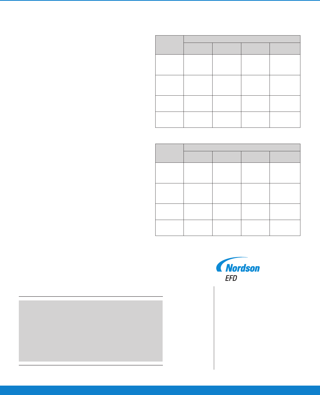
Spray Patterns
Round Pattern Spray Area Coverage
Nozzle
Nozzle Distance from Work Surface
25.4 mm
1.0"
50.8 mm
2.0"
76.2 mm
3.0"
152.4 mm
6.0"
#7007021
Standard
1.17 mm
(0.046")
6.35 mm
0.25"
12.70 mm
0.50"
19.05 mm
0.75"
38.10 mm
1.50"
#7021783
Wide-angle
1.17 mm
(0.046")
19.05 mm
0.75"
38.10 mm
1.50"
50.80mm
2.00"
Not
recommended
#7007022
0.71 mm
(0.028")
5.08 mm
0.20"
10.16 mm
0.40"
15.24 mm
0.60"
30.48 mm
1.20"
#7007023
0.36 mm
(0.014")
4.32 mm
0.17"
8.64 mm
0.34"
12.70 mm
0.50"
25.40 mm
1.00"
Fan Pattern Spray Area Coverage
Nozzle
Nozzle Distance from Work Surface
25.4 mm
1.0"
50.8 mm
2.0"
76.2 mm
3.0"
152.4 mm
6.0"
#7021787
Standard
1.17 mm
(0.046")
25.40 mm
1.00"
38.10 mm
1.50"
50.80 mm
2.00"
82.55 mm
3.25"
#7021784
Wide-angle
1.17 mm
(0.046")
38.1 mm
1.50"
63.5 mm
2.50"
82.55 mm
3.25"
165.1 mm
6.50"
#7021876
0.71 mm
(0.028")
10.16 mm
0.40"
20.32 mm
0.80"
30.48 mm
1.20"
60.96 mm
2.40"
#7021785
0.36 mm
(0.014")
8.63 mm
0.34"
17.27 mm
0.68"
25.4 mm
1.00"
50.8 mm
2.00"
Specifications
781S and MM781-SYS
Weight: 235.3 g (8.29 oz)
Fluid body: Hard-coated aluminum
Air cylinder body: Hard-coated aluminum
781S-SS / 781RC-SS*
Weight: 405.3 g (14.29 oz)
Fluid body: 303 stainless steel
Air cylinder body: 303 stainless steel
General
781S Size: 104.6L x 26.9DIA mm (4.12" x 1.06")
781RC Size: 114.91L x 26.92DIA mm (4.52" x 1.06")
Air cap: 303 stainless steel
Piston: 303 stainless steel
Needle and nozzle: 303 stainless steel
Free flow orifice: 1.17 mm (0.046"), 0.71 mm (0.028"), or
0.36 mm (0.014")
Needle packings: PTFE
*Fluid outlet thread: 1/8 NPT female (recirculation models
only)
Mounting: (1) 1/4-28 UNF tapped hole
Air pressure required: 4.8–6.2 bar (70–90 psi)
Maximum input fluid pressure: 20.7 bar (300 psi)
Maximum operating temperature: 102º C (215º F)
Operating frequency: Exceeds 400 cycles/min
*781RC-SS has an additional 1/8 NPT outlet port for fluids
requiring recirculation back to the primary reservoir. the
recirculation process keeps fluid moving so solids remain in
suspension.
All stainless steel valve parts are passivated.