80S15贴片机电路图.pdf - 第116页
OPTIONS 3 - I Sipl ace 8 0 S-1 5 circ uit di agr ams Content s Edition 05/9 8 Drawing no. Designation Chapter/Page 3 SIPLACE 80S-15/OPTIONS Circuit Diagrams 1710460- E6000-00 0-02-L-02 -4 Nozz le chang er for rev olver h…
2 - 71
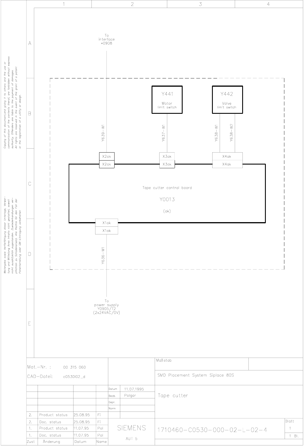
1710460-C0530-000-02-L-02-4 Tape cutter
OPTIONS 3 - I
Siplace 80 S-15 circuit diagrams Contents
Edition 05/98
Drawing no. Designation Chapter/Page
3 SIPLACE 80S-15/OPTIONS Circuit Diagrams
1710460-E6000-000-02-L-02-4 Nozzle changer for revolver head (Siplace 80S) (Sh. 1 of 2) 3 - 1
1710460-E6000-000-02-L-02-4 Nozzle changer for revolver head (Siplace 80F) (Sh. 2 of 2) 3 - 1
1710470-Y0096-000-01-N-01-4 Control board, nozzle changer 3 - 2
1710460-J3300-000-01-L-01-4 PCB barcode Siplace 80S/F (bottom) (Sh. 1 of 2) 3 - 3
1710460-J3400-000-01-L-01-4 PCB barcode Siplace 80S/F (top) (Sh. 1 of 2) 3 - 3
1710470-Y0457-000-02-L-02-4 Bero: ceramic substrate centering 3 - 4
1710470-Y0661-000-01-L-01-4 Cable: valve - ceramic substrate centering 3 - 4
1710460-Y0591-000-01-L-01-4 Connection cable: Siplace --> Siplace 3 - 5
1710460-Y0592-000-01-L-01-4 Connection cable: Siplace --> HS180/SP120 3 - 5
1710470-Y0921-000-05-F-05-4 Conversion instructions for SIPLACE from 230/400 V to 110/208V (Sh. 1 of 2) 3 - 6
1710470-Y0921-000-05-F-05-4 Conversion instructions for Siplace from 230/400V to 110/208V (Sh. 2 of 2) 3 - 6
1710470-Y0921-000-05-L-05-4 Conversion instructions for Siplace from 230/400V to 110/208V (Sh. 1 of 6) 3 - 7
1710470-Y0921-000-05-L-05-4 Conversion instructions for Siplace from 230/400V to 110/208V (Sh. 2 of 6) 3 - 7
1710470-Y0921-000-05-L-05-4 Conversion instructions for Siplace from 230/400V to 110/208V (Sh. 3 of 6) 3 - 8
1710470-Y0921-000-05-L-05-4 Conversion instructions for Siplace from 230/400V to 110/208V (Sh. 4 of 6) 3 - 8
1710470-Y0921-000-05-L-05-4 Conversion instructions for Siplace from 230/400V to 110/208V (Sh. 5 of 6) 3 - 9
1710470-Y0921-000-05-L-05-4 Conversion instructions for Siplace from 230/400V to 110/208V (Sh. 6 of 6) 3 - 9
1710470-Y0964-000-02-F-02-4 Interface simulation, SIPLACE previous station (Sh. 1 of 2) 3 - 10
1710470-Y0964-000-02-F-02-4 Interface simulation, SIPLACE previous station (Sh. 2 of 2) 3 - 10
1710470-Y0964-000-02-L-02-4 Interface simulation, SIPLACE previous station 3 - 11
1710470-Y0965-000-02-L-02-4 Interface simulation, SIPLACE following station 3 - 11
1710470-Y0965-000-02-F-02-4 Interface simulation, SIPLACE following station (Sh. 1 of 2) 3 - 12
1710470-Y0965-000-02-F-02-4 Interface simulation, SIPLACE following station (Sh. 2 of 2) 3 - 12
1710470-Y0600-000-01-L-01-4 Cable, external power supply 3 - 13
1710470-F0915-000-01-L-01-3 Option, RLCD tester 3 - 14
1710470-F0915-000-01-T-01-3 Option, RLCD tester (control unit section) 3 - 15
1710470-Y0570-000-02-L-02-4 Cable: RLCD measurement cable 3 - 16
1710491-Y3014-000-01-L-04-4 Cable: measurement jaws - centering station, gantry board, type 2 3 - 16
1710460-Y0568-000-02-L-06-4 Cable control unit - conversion board (RLCD tester) 3 - 17
1710460-Y0568-000-02-M-01-4 Cable control unit - conversion board (RLCD tester) 3 - 17
3 - II OPTIONS
Drawing no. Designation Chapter/Page
Contents Siplace 80 S-15 circuit diagrams
Edition 05/98