Heated Stage App Note.pdf - 第4页
What’ s going on during reow? Application Note AN-HS-100918-V1 www .nordsondage.com Americas + 1 760 930 3307 sales@nordsondage.com Europe +44 1296 317800 globalsales@nordsondage.com China +86 512 6665 2008 sales.ch@nor…
What’s going on during reow? Application Note
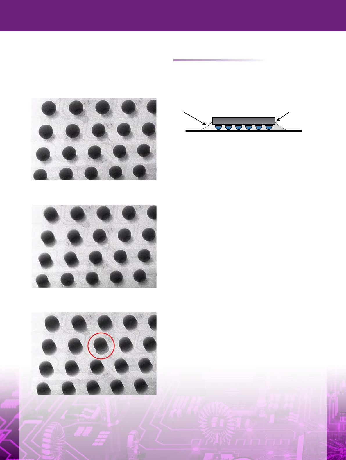
Figures 3, 4 and 5 are X-ray images showing HIP
forming in real-time. Figure 3 shows a BGA after
placement but before heating. The solder begins
to reow at 230°C as shown in Figure 4. Figure
5 shows the HIP defect fully formed and clearly
different from the other connections.
Figure 4: X-ray image from the Heated Stage. Reow
begins on outer connections rst at around 230°C .
Figure 5: X-ray image from the Heated Stage showing HIP
defect forming.
Underll is not always your friend
There are ever increasing demands on portable
electronics for greater functionality, higher reliability and
mechanical toughness. OEMs are looking for solutions
for better heat distribution and impact resistance for
components like BGA. One such solution is underll.
Figure 6: Underll placement beneath BGA.
Underll is a liquid or polymer sometimes applied to a
corner or one edge of the component. The PCB and
component are heated to between 125°C and 165°C.
Capillary action then draws it under the device and
encapsulates the connections. Once cured, underll
will minimize the expansion differences of materials so
device and PCB are held together more rmly. This
reduces working life stresses on the roots of the
solder balls.
Should one of these high value products fail to meet
quality control, usually it will be reworked. This can lead
to components with underll, near the rework area,
being subjected to reow temperatures for a second
time. Under these conditions the underll will hold the
device and PCB together as designed. But now this
property can be potentially harmful. What happens is
revealed in real-time using the Heated Stage
(Figures 7 to 9).
The following example illustrates the typical behaviour of
BGAs with cured underll that are exposed to elevated
temperatures during PCB rework. The device in question
is mounted in the Heated Stage and the temperature is
increased. The solder joints are monitored in real-time
on the X-ray system screen. The video of the process
is also recorded. When the temperature reaches 230°C
the solder connections start to deform and expand.
However, due to the cured underll, there is not enough
ex in the device/PCB assembly to compensate for
the expanding solder, Thus resulting in solder being
squeezed out, growing solder beads around the device,
solder bridging and solder joints that are severely
compromised (Figure 8). In some extreme cases the
BGA balls simply explode (Figure 9).
The Heated Stage provides critical insight into the
processes during reow. In this case, great care needs
to be taken when reworking PCBs with underll.
Figure 3: X-ray image from the Heated Stage before
reow. BGA placed on solder paste deposits.
Underll BGA die
PCB substrate
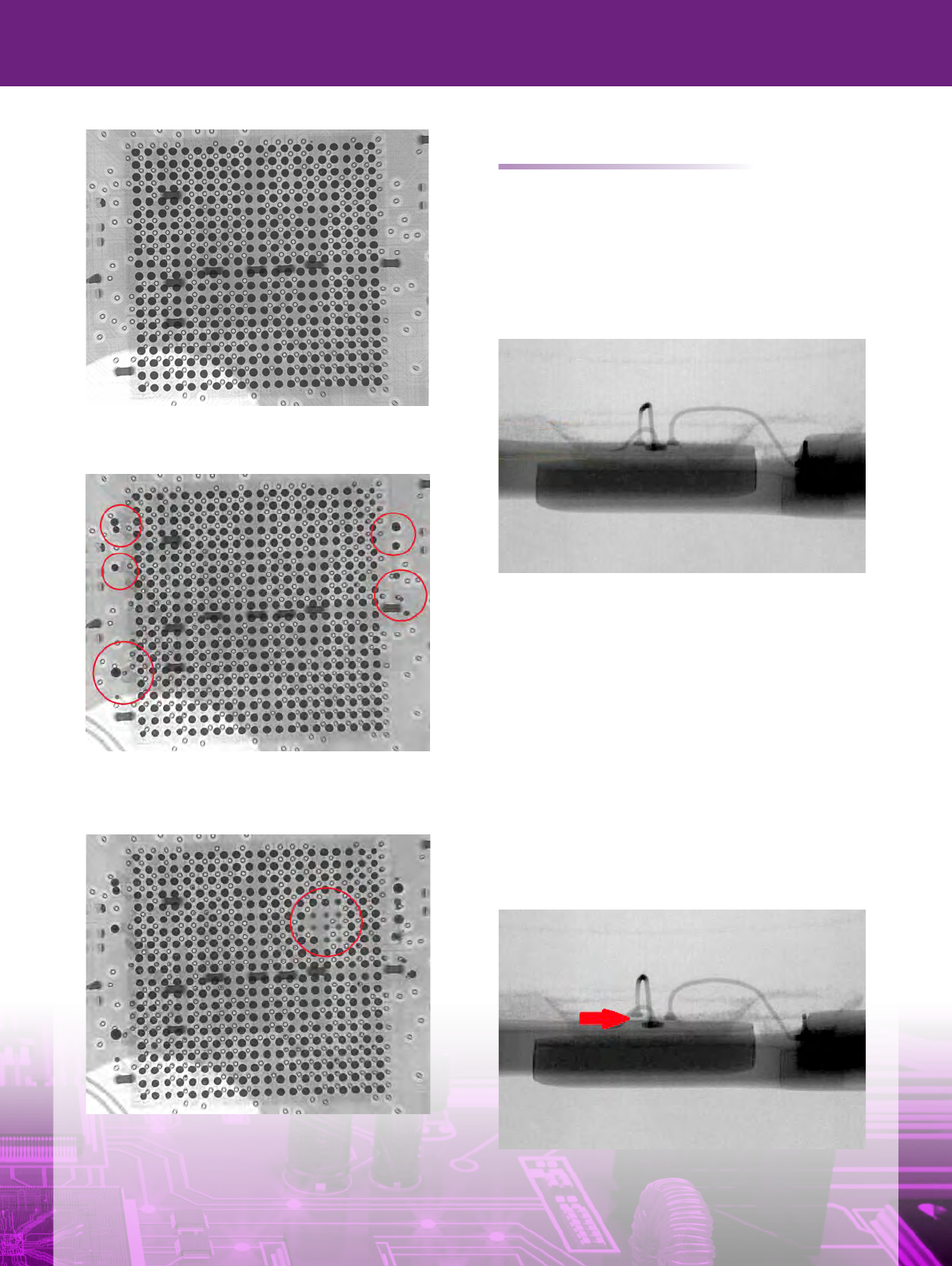
Figure 7: X-ray image from the Heated Stage. BGA with
underll before second reow.
Figure 8: X-ray image from the Heated Stage. Liquidus
temperature is reached. Solder is seen to be leeching out
away from the device.
Figure 9: X-ray image from the Heated Stage. As the heat
continues to rise eight connections explode.
Bond wire delamination
Some defects are impossible to see during the
inspection stage at the end of the production
process. This can mean that a product may have
failed tests but with no clear answer as to why.
In the following example one such case is
investigated (Figures 10 to 12).
Figure 10: X-ray image from the Heated Stage. Side view of
a small LED, showing the bond wires connected to the die
surface before applying heat.
It was known that this type of LED failed to work
post-reow but the exact failure mode was not
conrmed.
A fresh device was mounted in the Heated Stage and
the effects of the reow temperatures on the LED,
were investigated in real-time.
At around 195°C one of the bond wires has become
lifted (Figure 11). Critically this has happened before
the solder connecting it to the PCB has reowed.
Figure 11: X-ray image from the Heated Stage. Bond wire
showing clear separation from the die surface, around 195°C.

What’s going on during reow? Application Note
AN-HS-100918-V1
www.nordsondage.com
Americas + 1 760 930 3307
sales@nordsondage.com
Europe +44 1296 317800
globalsales@nordsondage.com
China +86 512 6665 2008
sales.ch@nordsondage.com
Germany
+49 89 2000 338 270
sales.de@nordsondage.com
Japan +81 3 3599 5920
sales.jp@nordsondage.com
South East Asia +65 6552 7533
sales.sg@nordsondage.com
Taiwan +886 2 2902 1860
globalsales@nordsondage.com
United Kingdom
+44 1296 317800
globalsales@nordsondage.com
Where can I find out more?
1. Videos available via the QR code link.
2. Heated Stage Reow Simulator Inspection Option Data Sheet.
Figure 12: X-ray image from the Heated Stage. Bond wire
showing no signs of defect post cooling.
During cooling the bond wire goes back onto the
surface of the die (Figure 12). This explains why the
open defect could not be detected post reow.
In summary, the Heated Stage Simulator provides
critical and unique capability for detecting bond wire
lifting in LEDs during reow.
A link to the real-time videos for each of these case
studies is provided in the ‘Where can I nd out more’
section below.
Figure 2 courtesy of Bob Willis 2014