instructionmanual_power-line_en.pdf
f_3 Instruction Manual 1. Connection Method (1) Single-Phase Both positiv e bloc k terminal ear th terminals are connected to a metal case, and as a result, both can be connected to the frame ground of the electronic de …
f_3
Instruction Manual
1. Connection Method
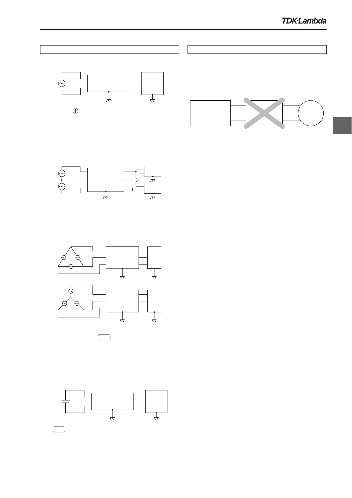
(1) Single-Phase
Both positiv
e
block terminal earth terminals are
connected to a metal case, and as a result, both can be
connected to the frame ground of the electronic device.
They can also be used as grounding terminals.
(2) Single-Phase Three-Line
A three-phase three-line noise filter can be used in single-
phase three-line systems.
(3) Three-Phase Three-Line
DeviceNoise Filter
1
2
3
6
5
4
DeviceNoise Filter
1
2
3
6
5
4
Both block terminal type
FG
are connected to a metal
case, and as a result, both can be connected to the frame
ground of the electronic device.
They can also be used as grounding terminals.
(4) DC Input
Noise Filter
Electronic
Device
1
2
4
3
Both
FG
terminals are connected to a metal case, and
as a result, both can be connected to the frame ground of
the electronic device. They can also be used as grounding
terminals.
2. Handling Warnings
(1) The standard noise lter cannot be used between
a general-purpose inverter and a motor.
Please select a specialized filter f
or the general-purpose
inverter output side.
MotorNoise Filter
General-Purpose
Inverter
(2)Use with direct current and commercial
frequencies (50/60 Hz).
If used at a frequency other than commercial frequencies
,
inquire with a TDK-Lambda sales representative in
advance.
(3)The DC line specialized noise lter cannot be
used on AC lines.
(4)Leakage Current
The noise filter has inter
nal line bypass capacitor built-in,
and as a result, leakage current flows.
When selecting an electric leakage breaker, take into
consideration the leakage current of the noise filter.
(5)Permissible Inrush Current
If the back of the noise filter is connected to a switching
power supply, a large inrush current will flow when the
input power is turned on.
If the inrush current duration is approximately one-
quarter cycle of a 50/60 Hz commercial power supply,
the permissible current value is 50 times as much as the
rated current.
Noise Filter
Electronic
Device
1
2
4
3
200V
Device
100V
Device
Three-Phase
Noise Filter
1
2
3
6
5
4
EMC
filter
web171225
f_4
3. Noise Filter Safety Standards
Each country has the following safety standard on noise
filters.
Refer to each product catalog for acquired standards.
United States: UL1283
Canada: CSA C22.2 No.8
Europe: EN60939
CE Markings
Devices (final set products) that meet European EMC
Directive is mandatory to apply CE Marking.
As a result, most of the products in this catalog that
categorized as component do not apply CE markings.
If you look for the products in this catalog for use in
CE marking devices, please select European safety
standards certificated products.
CCC Certication
Noise filters are exempt from CCC certification.
4.
Methods of Measuring Characteristic Data
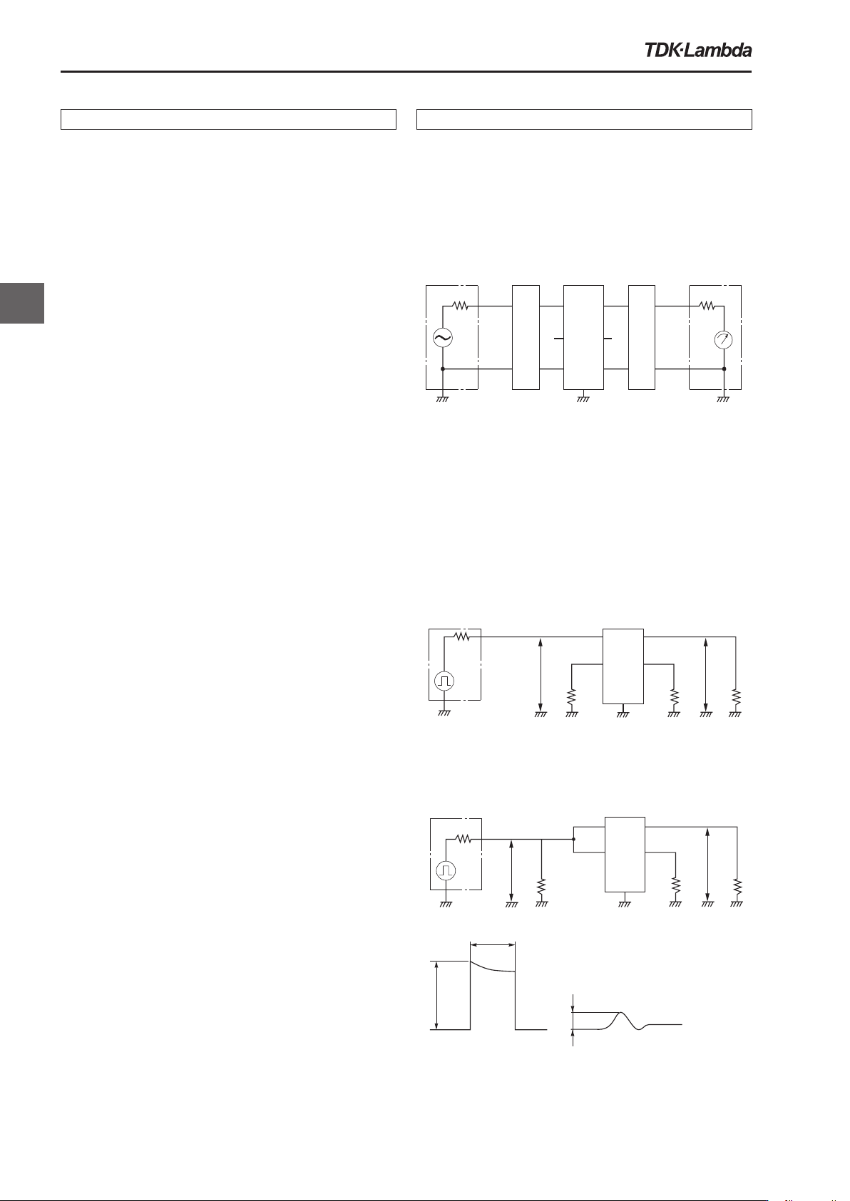
(1)Method of measuring insertion attenuation
Measurement of attenuation when an EMC filter is
inserted in a circuit generally complies with the Military
standard (MIL-STD-220), but many Power Line EMC
Filters of TDK-Lambda brand use are measured in
accordance with the following measurement method.
S.G.
50Ω
R
1
R
2
T
1
T
2
S1 S2
50Ω
L.M.
EMCfilter
Balun
Balun
Attenuation=20log10 E2/E1 [dB]
E
1: Level when an EMC filter is inserted in the circuit
E
2: Level when an EMC filter is not inserted in the circuit
The baluns in the circuit contain change-over switches so that stand-alone
measurements can be made for the differential mode (symmetrical wave)
portion and the common mode (asymmetrical wave) portion.
(2)Method of measuring pulse attenuation
(a)
Diff
erential mode (symmetrical wave) portion
measurement circuit
50Ω
50Ω
50Ω
50Ω
V 1
V
0
Noisesimulator
EMCfilter
1 4
32
(b) Common mode (asymmetrical wave) portion
measurement circuit
50Ω
50Ω
50Ω
50Ω
V
1
V
0
Noise simulator
1μs
V
1
V
0
Inputpulsewaveform Outputpulsewaveform
EMC filter
1 4
32
Instruction Manual
EMC
filter