RV-2-3D_SPE_EN.pdf - 第7页
RV - 2 PRODUCT SPECIFICA T IONS 4 5. Inspection Function S pecification Item Spe cification T y pes of boards tha t can b e inspecte d After solder pr inting , before ref low , after ref low Parts that can be ins pected …
RV-2 PRODUCT SPECIFICATIONS
3
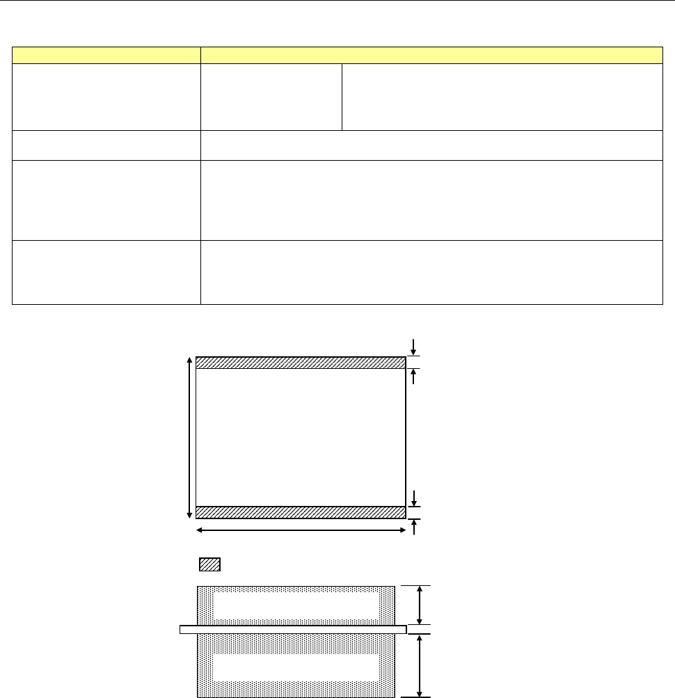
4. Applicable Boards
Applicable board specification
Item
Specification
External board dimensions Single mode
Standard specifications:
50 (W) x 50 (D) to 410 (W) x 300(D) mm
long size specification:
50(W)
×
50(D)
~
630(W)
×
300(D) mm
Board thickness 0.3 to 8.0 mm
Maximum board height
Standard Top side: 40 mm Bottom side: 70 mm
* 20 to 60 mm can be accommodated as the height on the top side by
changing the height of lighting.
(Selectable at the time of purchase)
Payload
4.0 kg or less (The transfer speed is changed variably according to the
payload.)
* Please consult us if the weight exceeds the limit.
∗ The maximum board dimensions need to be changed according to the board weight and shape.
Loading a board having a part whose height exceeds 40 mm on the top side or 70 mm on the bottom side
may damage the board or cause the device to malfunction. (The above dimensions provide clearances
from the lights when boards are transferred and inspected.)
Board fixture part of inspection
• Single mode
3 mm
50 to
360 mm
50 to 410 mm
3 mm
PWB
PWB thickness:
0.3 to 8.0 mm
40 mm
* 20 to 60 mm can be accommodated by changing
70 mm
Clearance above board
Clearance below board

RV-2 PRODUCT SPECIFICATIONS
4
5. Inspection Function Specification
Item
Specification
Types of boards that can be
inspected
After solder printing, before reflow, after reflow
Parts that can be inspected
Parts gap 0.3 mm or more, square chips of 0603 or more, cylindrical
chips,
tantalum capacitors, aluminum chip capacitors, transistors,
SOP/QFP (0.3 mm or greater pitch), connectors,
leads of discrete parts
* When selecting the optional lens of 10μm/pixel
Parts gap 0.2 mm or more, square chips of 0402 or more
Inspection item
Lack of parts, offset, polarity, front-side back, no solder, bridge, solder
amount, Part's height, lead floating
disconnected insertion part, etc.
* Optional: Character-recognition (OCR/OCV), code reader (1D, 2D)
6. Hardware Specification
Item
Specification
Image processing system
Color image processing
• 400-million-pixel CMOS color camera
• Image processing library HALCON11
• High-brightness white LED 3-stage lighting + coaxial illumination
Resolution Standard: 15.0 μm/pixel Optional lens: 10.0 μm/pixel
Image range Standard: 30.0 x 30.0 mm Optional lens: 20.0 x 20.0 mm
Transfer conveyor type Single track
Transfer conveyor width
adjustment
Automatic adjustment
Height of transfer
conveyor
900 mm -20 mm to +70 mm Adjustable using the adjuster feet
Processing time 0.41 second/ 1 screen (In the maker optimum)
Positioning Reference on end face of board
Control computer OS Windows 7, 64-bit
External code reader
Communication IF: RS-232C
* Please contact us for the recommended equipment.
Network 100 Mbps Ethernet or faster (1 Gbps Ethernet recommended)

RV-2 PRODUCT SPECIFICATIONS
5
7. Option
7-1. Optional Software
Item
Specification
Main system
• Character-recognition (OCR/OCV)
• Code reader (1D, 2D)
• Communication license
* Required when connecting to a data server
Peripherals
* It is your responsibility to
prepare a PC.
• Remote judgment (CCC mode)
• Remote judgment (OLR mode)
• Repair station
• SPC
• Offline editor
• Quality Traceability
Server system
* It is your responsibility to
prepare a PC.
• Data server
* Required when connecting an optional peripheral software.
• Data share (Release plan: Please contact us for details.)
7-1-1. Optional Main System Software
Character-recognition (OCR/OCV)
This OCR (Optical Character Recognition) is a support tool that recognizes an alphanumeric character
string written on the board or part and converts it into the character data that can be handled on the
computer so as to make the judgment.
Resistance constants, IC characters, etc., can be recognized.
This OCV (Optical Character Verification) is a support tool that recognizes characters using the pattern
matching.