Nordson_EFD_Series_400_Instructions.pdf
Series 400 Autovalve Instructions / Parts Lists Electronic pdf files of Nordson EFD manuals are also available at www.nordsonefd.com ™ Maximum operating pressure 235 bar (3500 psi)
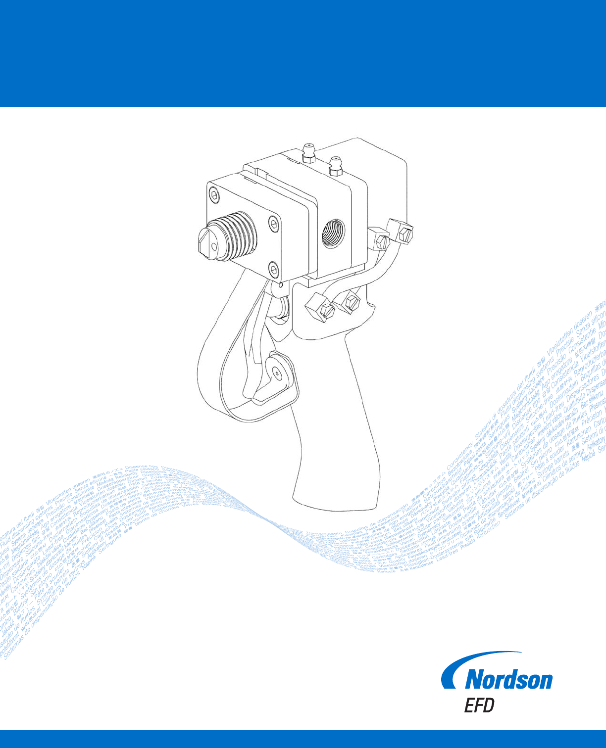
Series 400 Autovalve
Instructions / Parts Lists
Electronic pdf files of Nordson EFD
manuals are also available at
www.nordsonefd.com
™
Maximum operating pressure
235 bar (3500 psi)

Series 400 Autovalve | Instructions / Parts Lists
2 www.nordsonefd.com info@nordsonefd.com +1-401-431-7000 Sales and service of Nordson EFD dispensing systems are available worldwide.
Contents
Contents ........................................................................................................................................................................................ 2
Operation .......................................................................................................................................................................................3
Installation .....................................................................................................................................................................................3
Connect Supply Lines ................................................................................................................................................................3
Startup .......................................................................................................................................................................................3
Maintenance ..................................................................................................................................................................................4
Disassembly and Cleaning ........................................................................................................................................................4
Rebuilding the Autovalve ........................................................................................................................................................... 4
Final QC Check ..........................................................................................................................................................................4
Manifolds for Series 160 Disposable Mixers .................................................................................................................................6
Mount ............................................................................................................................................................................................7
Hand Held with Pneumatic Switch #7701977 ...........................................................................................................................7
Hand Held — Electric Momentary Switch (24 Volt) #7701971
Hand Held — Electric Push On/Off Switch (24 Volt) #7701973 ................................................................................................8
Air Cylinders — Single Hardened SS Shafts #7702315 ................................................................................................................9
Air Cylinders — Double .................................................................................................................................................................9
Spare Parts Kits ..........................................................................................................................................................................10
Accessories ................................................................................................................................................................................. 11
Fluid Inlet Adapter for 400 Valve ..............................................................................................................................................11
Ratio Check Cap ......................................................................................................................................................................12
Night Cap .................................................................................................................................................................................12
Troubleshooting ..........................................................................................................................................................................13

Series 400 Autovalve | Instructions / Parts Lists
3www.nordsonefd.com info@nordsonefd.com +1-401-431-7000 Sales and service of Nordson EFD dispensing systems are available worldwide.
Operation
The ON-OFF operation of the valve is controlled by movement of the piston inside the air cylinder (1). In the OFF position, the
piston advances and the front seal (13) seats into the seat plate (8).
In the ON position, the piston and seals retract from the seat plate (8), which allows A & B fluids to pass through the manifold.
A disposable Series 160 mixer can be attached to the manifold. If the operating pressure exceeds 10bar (150psi), we
recommend a metal jacket be used over the plastic mix tube.
NOTE: For all reference numbers in parenthesis, see pages 5–9.
Your 400 AUTOVALVE in general...
• Designed to dispense two-component adhesives and sealants
• Dispenses low or high viscosity urethanes, epoxies and silicones
• Can be mounted for beads or timed shots; optional handle is available for hand held applications
• Provides an ON-OFF function. The metering of the adhesives in the proper ratio of A:B is controlled by the metering
pumps.
Installation
Connect Supply Lines
The A & B fluid hoses are connected to the side of the valve body (7), between the valve and the pumps, and should be as
short as possible. It is a good practice to install check valves in the hoses just before the valve. Optional fitting with check
valve is listed on page11.
For stationary mount, the air lines will be connected to the side of the air cylinder (1). Air to the back of the cylinder to close
and air to the front to open. If the optional handle is used, air is connected to the barbed fitting (105) on the side of the
handle.
The air line should have minimum pressure of 5.5bar (80psi).
Startup
1. With the hand-held model, start metering pumps and purge the air out of the A & B hoses and Autovalve. After the A and
B fluids come out of the manifold, attach a mixer to the manifold and hold the valve upside down with the mixer pointing
up. Dispensing A & B will purge the last pockets of air in the valve body.
A stationary mount or gantry installation requires a swivel mounting bracket. To complete purging, turn the valve with the
mixer pointing up and dispense A & B.
2. Take a ratio check by weight of A:B after the manifold. The Autovalve does No Metering. The Volume Ratio of A:B is
controlled by the metering pumps. However, between the metering pumps and the Autovalve are hoses. These hoses
will expand under pressure and cause lead-lag problems. Lead-lag refers to the uneven starting of the A fluid before the
B fluid. Nordson EFD offers 1:1 and wide ratio manifolds to reduce this problem. The selection of the correct manifold
depends on both the volume and viscosity ratio of A and B.
Consult EFD Technical Services for details at 800-556-3484.