BA-PM400-500-english-D08853.pdf - 第6页
and insert screws with disk springs , and tighten them until the screw heads are just fully seated (do not completely tighten them!). The concave side of the first three disc springs must point away from the screw …
disposed of.
Use only original KNF replacement
parts.
Parts and tools required:
1 Service Set (see section 7)
Screwdriver blade width 2 mm
Phillips screwdriver No. 2
Felt-tip pen.
Change the diaphragms and valve pla-
tes/sealings in the following sequence:
a) Preparatory steps
b) Removing pump head
c) Changing diaphragm
d) Changing valve plates/ sealings
e) Refitting pump head
f) Final steps.
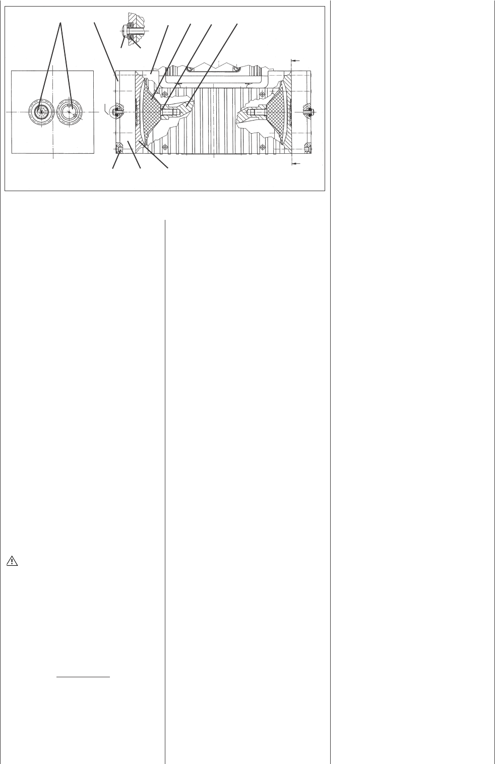
The position numbers in the
following text refer to fig. 2.
a.) Preparatory Steps
Shut down system (see section 4.2)
including disconnecting the pump
from the power source (pull out
plug of pump).
Remove tubing from the inlet and
outlet connectors of the pump.
On the pneumatic head connec-
tions, loosen one of the union nuts
by hand. Then slightly loosen the
angle-fitting in the pump head by
turning it anticlockwise
, so that the
connecting tube can be pulled out
Undo the screws that hold the
fan cover (see fig. 1) and remove
the fan cover from the motor.
b) Removing pump head
(for each head separately)
Mark the position of top plate ,
head plate , intermediate plate
, and housing relative to each
other with a felt-tip pen. This is to
ensure that the parts will be re-
assembled cor rectly at a later
stage.
Undo the eight screws and lift
the pump head off the housing .
The solenoid valve of the
drying system remains fitted
in this situation.
c) Changing diaphragm
Position the pump so that the dia-
phragm surface is upwards.
Turn the fan to bring the structured
diaphragm to top dead centre.
Using a small screwdriver, bet-
ween the housing and the outer
edge of the structured diaphragm,
carefully lift the edge of the dia-
phragm lightly upwards at one
point (making sure not to damage
the housing). Now grip the edge of
the diaphragm on opposite sides,
unscrew it by turning anti-clock-
wise.
Take the diaphragm spacer(s) off
the connecting rod and retain
them.
Check that all parts are free from
dirt and clean them if necessary.
Put the diaphragm spacer(s)
on the thread of the new dia-
phragm.
Fit the new structured diaphragm
: hold the connecting rod with
one finger, and gently screw in
(clockwise) the structured dia-
phragm with diaphragm spacers.
Turn the fan until the structured
diaphragm is at the top dead cent-
re. Using a small screwdriver, bet-
ween the housing and the outer
edge of the structured diaphragm,
carefully lift the edge of the dia-
phragm lightly upwards at one
point. Now grip the edge of the dia-
phragm on opposite sides (do not
overstretch the diaphragm!) and
tighten the structured diaphragm
clock-wise.
d) Changing valve plates/sealings
Undo the two screws .
Separate the head plate with
top plate from intermediate
plate .
Remove the valve plates/sealings
from the intermediate plate.
Check that the valve seats, the
head plate and intermediate plate
are clean. If scratches, distortion,
or corrosion are evident on these
parts they should be replaced.
Lay the new valve plates/sealings
in the recesses in the interme-
diate plate. The valve plates/sea-
lings for suction and pressure sides
are identical, as are upper and
lower sides of the plates/sealings.
e) Refitting pump head
Turn the fan to bring the structured
diaphragm to medium position.
Place the intermediate plate ,
with valve plates/sealings on
the housing, in the position indica-
ted by the felt-tip pen marking.
Place the head plate on the
intermediate plate in the posi-
tion indicated by the felt-tip pen
marking.
Place top plate in position
PM 16527-860.3-2.00 e 11/05
4
X
X
Fig. 2: Cross section of pump heads (symbolic)
Specification
Pos Description
Top plate
Head plate
Intermediate plate
Housing
Cross recessed raised counter-
sunk head screw
Structured diaphragm
Diaphragm spacers(s)
Connecting rod
Cross recessed raised cheese
head screw
Disk spring
Valve plate/Sealing

and insert screws with disk
springs , and tighten them until
the screw heads are just fully
seated (do not completely tighten
them!).
The concave side of the
first three disc springs must point
away from the screw head, the
next three towards it (see fig. 2,
detail X).
Gently tighten the screws ,
evenly and diagonally.
Turn the fan to check that the
pump rotates freely.
Now tighten screws hand-tight.
Tighten each of the screws a
half-turn more.
Repeat operations b), c), d), and e) for
the second pump head.
f) Final steps
Refit the the pneumatic head
connection:
Place tube onto the connecting
part of the angle fitting, turn angle
fitting to a straight position and
tighten the nut.
Refit the fan cover.
Reconnect the pump to the electri-
city supply.
If you have any questions about
servicing call our technical adviser
(see last page for contact tele-
phone number).
6. Troubleshooting
Sufficient vacuum is not reached
Possible reasons:
Tube connections are not tight
Condensate in the pump head
Switch the drying system on
or reduce the interval bet-
ween pump head ventilation
operations.
Diaphragms and/or valve plates/
sealings are worn out
Changing diaphragms and
valve plates/sealings:
see section 5.
If this problem occurs after chan-
ging of diaphragms and valve pla-
tes/ sealings:
See information in section 5.
Pump is switched on, but does not
run, the on/off-switch on the pump
is not lit
Possible reasons:
Pump is not connected with the
power source.
No voltage in the power source.
Fuse in the pump is defective (only
authorized/qualified personnel
should investigate this problem):
Disconnect the pump from
the power source by pulling
out plug.
Placement of fuse:
Fuse accessible after opening
the connecting box of the
pump (see fig. 1 for the posi-
tion of the connecting box).
Dimension of the fuse:
see section 8.
Pump is switched on, but does not
run, the on/off-switch on the pump
is lit
Possible reason:
The thermal switch has opened
due to overheating
Disconnect the pump from
the power source, let the
pump cool down, investigate
the reason for the overhea-
ting and irradicate it.
7. Ordering Information
Service Set
A Service Set contains all
replacement parts needed for one
complete service of the pump.
Service Set contains
2 diaphragms, 4 valve plates/sea-
lings
Order No.
047499
8. Specifications
Capacity: max. 60 l/min
Ultimate vacuum: 4 mbar abs.
Permissible operating pressure:
max. 1 bar
g
Permissible ambient
temperature: + 5... + 40 °C
Hose connection for tube ID 10 mm
Voltage pump: 230 V
Frequency: 50 Hz
Power consum-
ption pump: 220 W
Fuse pump
(2 x): 3.15 T [A]
IP 54
Voltage solenoid
valve 24 V DC
CE - Safety Demands
The pumps correspond to the
safety regulations of the EU low
voltage directive 73/23 EWG and of
the EU directive concerning elec-
tromagnetical compatibility 89/336
EWG. The requirements of the fol-
lowing harmonised standards are
fulfilled:
EN 55014
EN 61000-6-1
EN 61000-6-3
EN 61000-3-2/3
EN 61010-1
The pumps correspond to IEC 664:
the overvoltage category II
the pollution degree 2.
PM 16527-860.3-2.00 e 11/05
5

Appendix:
Customer statement for
repair order (sample
statement for copying)
In order for KNF to repair the
pump, the customer must provide
a statement on the media which
were pumped and on pump
cleaning. Please fill out the cor-
responding KNF form, and submit
it together with the pump.
Statement/Certificate
We confirm that the pump
model listed below
(please specify)
.............................................
.............................................
.............................................
Serial-No. (please specify)
.............................................
.............................................
.............................................
was used to pump the fol-
lowing media:
.............................................
.............................................
.............................................
.............................................
.............................................
.............................................
.............................................
and that the pump listed
above was cleaned. There
are no poisonous, aggres-
sive, biological, radioac-
tive or other dangerous
media in the pump.
................ ......................
Company Date/
Signature
PM 16527-860.3-2.00 e 11/05
6
KNF Neuberger GmbH
Alter Weg 3
D-79112 Freiburg
Tel. ++49/7664/5909-0
Fax ++49/7664/5909-99
E-Mail: info@knf.de
www.knf.de