aplication_note_i7090.pdf.pdf - 第3页
F i n d u s a t w w w . k e y s i g h t . c o m P a g e 3 Layout and Operational Overview for i7090 Assuming you are planning for the new line s etup for the i7090 and wish t o utilize the tester's bu ilt -in overhe…
Find us at www.keysight.com Page 2
Built-in bypass link conveyor
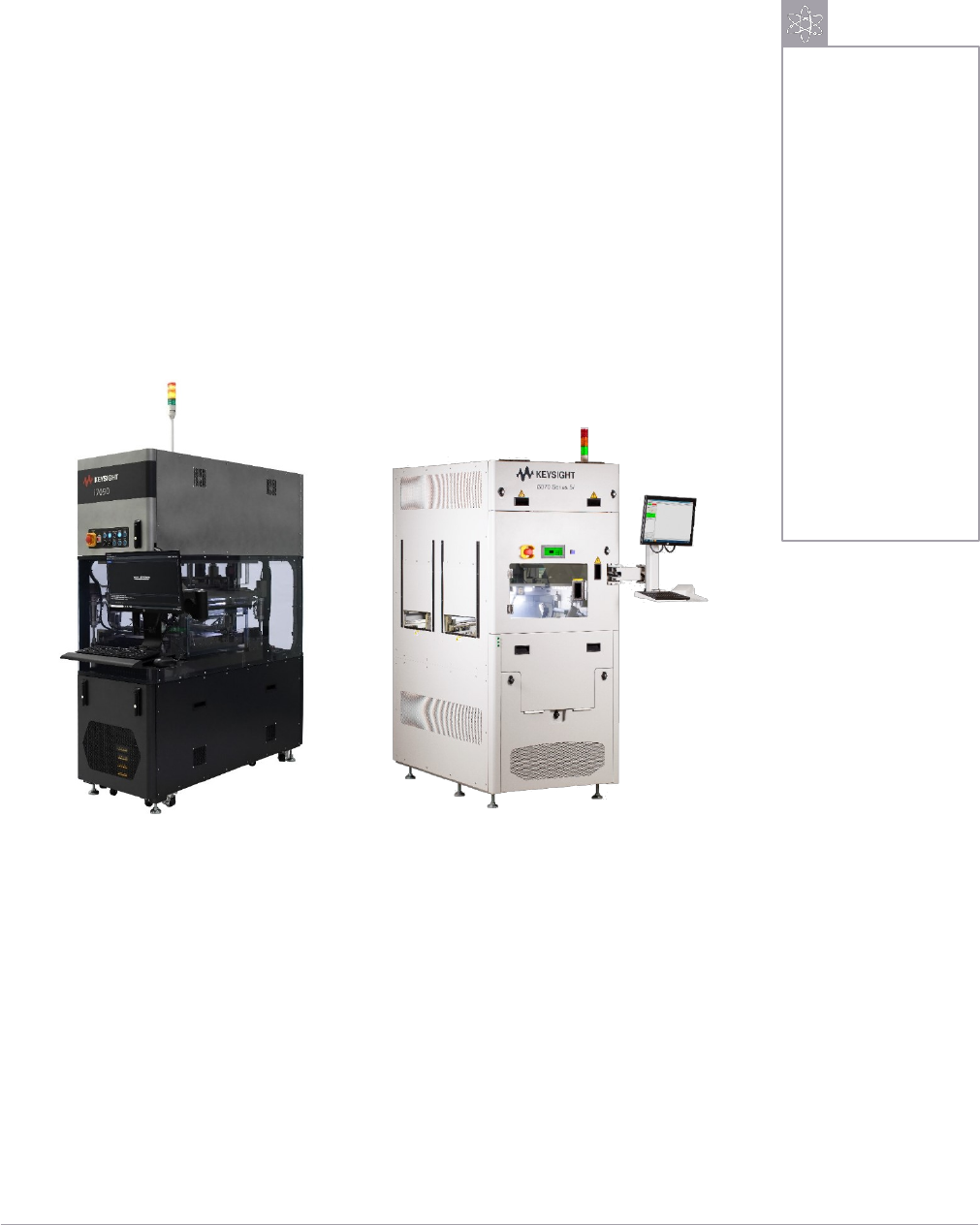
Keysight Inline In-Circuit Test (ICT) solution such as the recently launched
i7090, the first of its kind Massively Parallel Tester (MPT), and the i3070
2-module tester (E9988EL) have an option for you to customize the built-in
bypass link conveyor as shown in Figure 1.
The i7090 has an overhead built-in bypass link that runs parallel above the
test conveyor's fixed side. In contrast, the built-in bypass link for the i3070 is
located at the rear of the system so that the transport altitude aligns at the
same height for both the test and bypass conveyors. These built-in bypass
links can save you valuable floor space. Moreover, it is much easier to
implement on the manufacturing floor.
Figure 1. i7090 Massively Parallel Tester (Left), and E9988EL i3070 2-Module Tester (Right)
What is a Built-in
Bypass Link
Conveyor?
A built-in bypass link
conveyor is an optional
hardware feature to let
a PCB detour to the
next unutilized ICT if
two or more systems
are set up to meet the
production line rate.
Supported ICTs:
•
i7090
•
i3070
Find us at www.keysight.com Page 3
Layout and Operational Overview for i7090
Assuming you are planning for the new line setup for the i7090 and wish to utilize the tester's built-in
overhead bypass link to maximize the production yield, you will require a conveyor lifter to transport the
PCB to the overhead bypass link. The distance of the height between the test zone and bypass link
conveyor is 309.5 mm. If you are setting up the tester as SMEMA transport with a height of 950 mm,
you will need a lifter capable of lifting from 950 mm to 1259.5 mm. It would be best if you catered about
25 mm of tolerance for the travel distance of the lifter.
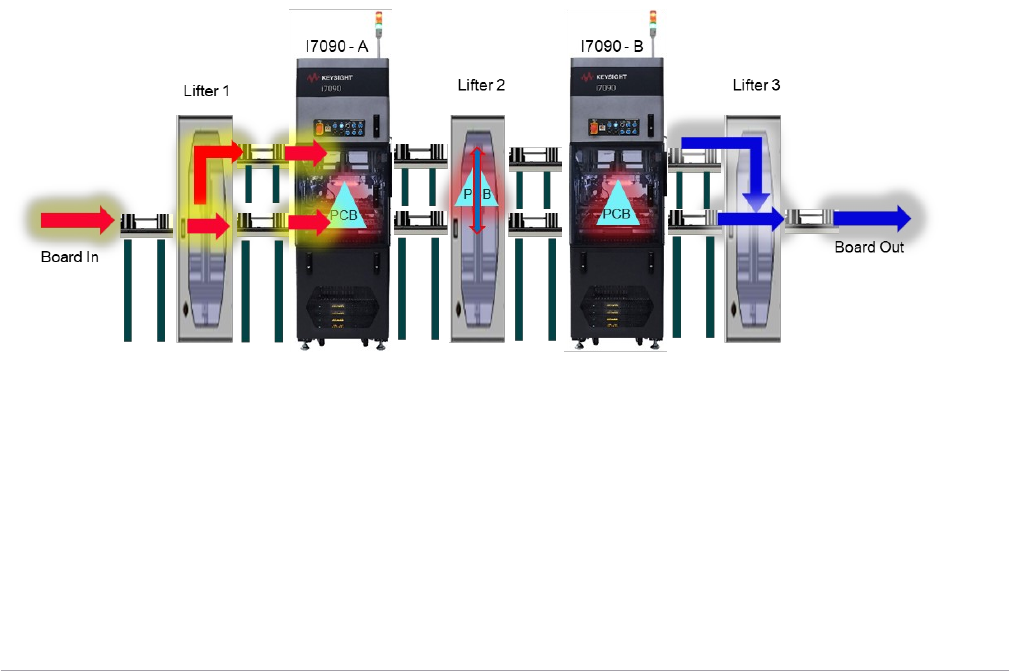
You can line up the systems adjacently with the link conveyor connected at each in and out feed, as
shown in Figure 2. Such a layout for the system is perfect for shortening the handling time with an
optimum beat rate. Besides, you could also benefit from good accessibility during periodic maintenance.
How does it work?
When the production line starts, the first PCB goes directly into the i7090-A, while the second incoming
PCB takes a detour to the i7090-B via the i7090-A's bypass link with the help of both Lifter-1 and Lifter-2
that is in place.
Upon completing the first PCB test in i7090-A, lifter-2 will transport it to the bypass link in i7090-B, and
lifter-3 will lower it back to the main conveyor link towards the end of the line and leave the station. As
for the second PCB that just completed the test in i7090-B, it goes straight to the next station following
the test, as there are no other systems beyond i7090-B, as shown in the diagram below.
Figure 2. i7090 system to system layout
Front View
Find us at www.keysight.com Page 4
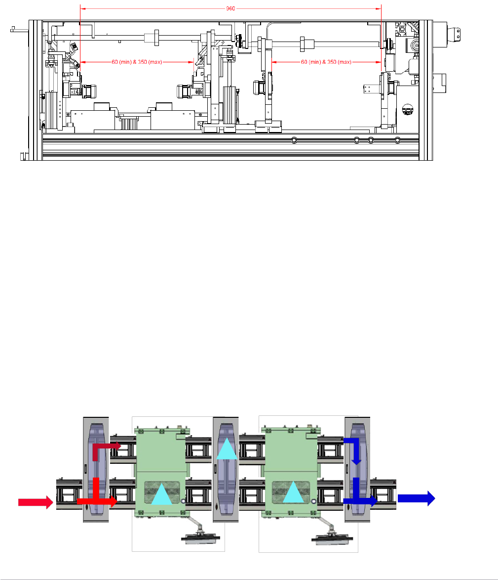
Layout and Operational Overview for i3070
The i3070 Inline ICT has the bypass link built-in at the rear of the system. In this case, you will need a
transversal capable of routing the PCB for 960 mm from the main conveyor link to the bypass link
(Figure 3).
Figure 3. Distance between test and bypass conveyor
Similar to i7090, you can line up the systems adjacently with the link conveyor connected at both in and
out feed of each system for the shortest handling time, as shown in Figure 4.
How does it work?
Likewise, instead of using a lifter, we will be using the transversal to do the routing of PCBs between the
main test zone and the bypass link conveyor. When the production line begins, the first PCB goes into
the i3070-A from the main link conveyor, while the second incoming PCB takes a detour to the i3070-B
via the i3070-A's bypass link with the help of both Transverse-1 and Transverse-2 that is in place.
Upon completing the first PCB test in i3070-A, Transverse-2 will transfer it to the i3070-B's bypass link,
and Transverse-3 routes it back towards the end of the main link conveyor and leave the station. Since
i3070-B is the last system in the station, the second PCB that just completed the test goes directly to the
next station from the main link conveyor following the test.
Board In
Top View
Board Out
Transverse 1
Transverse 2
Transverse 3
i3070 - A
i3070 - B
PCB
PCB
PCB
Figure 4. i3070 system to system layout