E6C3-C_Datasheet_en_201401_rev7_1.pdf - 第3页
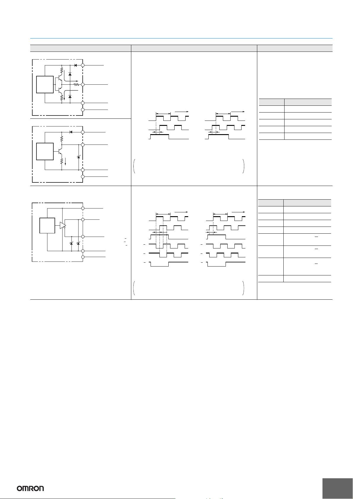
E6C3-C 3 I/O Circuit Diagrams Note: 1. The shielded cable o uter core (shield) i s not connected to the inn er area or to the case . 2. The phase A, phase B, and phase Z circuits are all identica l. 3. Normally, connect …
E6C3-C
2
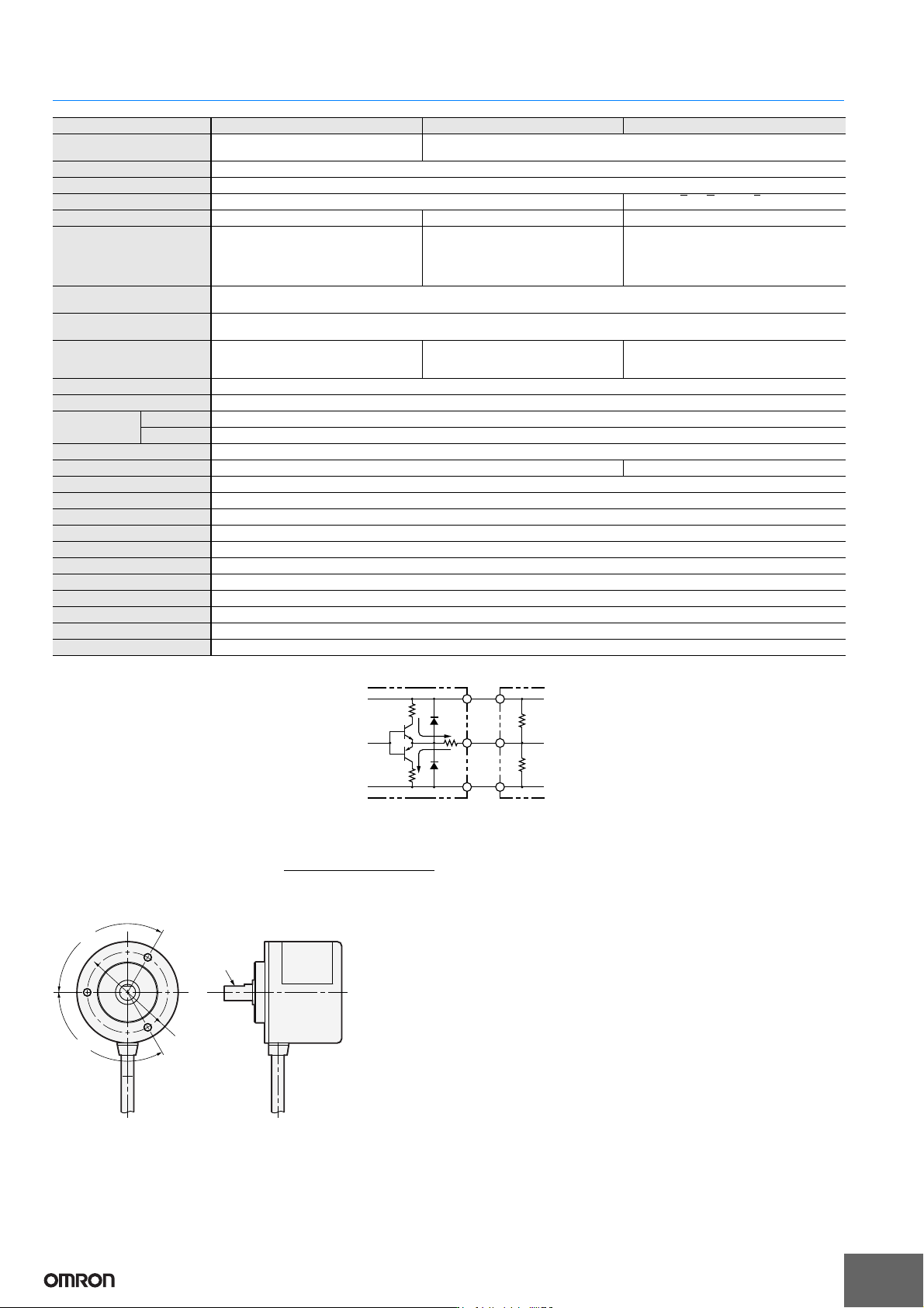
Ratings and Specifications
*1. An inrush current of approximately 9 A will flow for approximately 0.1 ms when the power is turned ON.
*2. Complementary Output
The complementary output has two output
transistors (NPN and PNP) as shown below. These
two output transistors alternately turn ON and OFF
depending on the high or low output signal. When
using them, pull up to the positive power supply
voltage level or pull down to 0 V. The
complementary output allows flow-in or flow-out of
the output current and thus the rising and falling
speeds of signals are fast. This allows a long cable
distance. They can be connected to open-collector
input devices (NPN, PNP).
*3. The line driver output is a data transmission circuit compatible with RS-422A and long-distance transmission is possible with a twisted-pair cable. (AM26LS31
equivalent)
*4. The maximum electrical response speed is determined by the resolution and maximum response frequency as follows:
Maximum electrical response speed (rpm) = × 60
This means that the Rotary Encoder will not operate electrically if its speed exceeds the maximum electrical response speed.
*5. The phase Z signal is output when cut face D on the shaft and the cable connection direction are as shown in the following diagram (output position range: ±15°).
Item Model E6C3-CWZ5GH E6C3-CWZ3EH E6C3-CWZ3XH
Power supply voltage
12 VDC −10% to 24 VDC +15%,
ripple (p-p): 5% max.
5 VDC −5% to 12 VDC +10%,
ripple (p-p): 5% max.
Current consumption*1 100 mA max.
Resolution (pulses/rotation) 100, 200, 300, 360, 500, 600, 720, 800, 1,000, 1,024, 1,200, 1,500, 1,800, 2,000, 2,048, 2,500, 3,600
Output phases Phases A, B, and Z*5 Phases A, A, B, B, Z, and Z
Output configuration Complementary outputs*2 Voltage output (NPN output) Line driver output*3
Output capacity
Output voltage: VH = Vcc -3 V min.
(IO = 30 mA)
VL = 2 V max.
(IO = −30 mA)
Output current: ±30 mA
Output resistance: 2 kΩ
Output current: 35 mA max.
Residual voltage: 0.7 V max.
AM26LS31 equivalent
Output current: High level: IO = −10 mA
Low level: IS = 10 mA
Output voltage: VO = 2.5 V min.
VS = 0.5 V max.
Maximum response
frequency*4
125 kHz (65 kHz when using phase Z reset)
Phase difference between
outputs
90°±45° between A and B (1/4 T ± 1/8 T)
Rise and fall times of output
1 μs max.
(Cable length: 2 m, Output current: 30 mA)
1 μs max.
(Cable length: 2 m, Output current: 35
mA)
1 μs max.
(Cable length: 2 m, IO: −10 mA,
IS: 10 mA)
Starting torque 10 mN·m max. at room temperature, 30 mN·m max. at low temperature
Moment of inertia 2.0 × 10
−6
kg·m
2
max.; 1.9 × 10
−6
kg·m
2
max. at 500 P/R max.
Shaft loading
Radial 80 N
Thrust 50 N
Maximum permissible speed 5,000 r/min
Protection circuits Power supply reverse polarity protection, Output load short-circuit protection ---
Ambient temperature range Operating: −10 to 70°C (with no icing), Storage: −25 to 85°C (with no icing)
Ambient humidity range Operating/Storage: 35% to 85% (with no condensation)
Insulation resistance 20 MΩ min. (at 500 VDC) between current-carrying parts and case
Dielectric strength 500 VAC, 50/60 Hz for 1 min between current-carrying parts and case
Vibration resistance Destruction: 10 to 500 Hz, 150 m/s
2
or 2-mm double amplitude for 11 min 3 times each in X, Y, and Z directions
Shock resistance Destruction: 1,000 m/s
2
3 times each in X, Y, and Z directions
Degree of protection IEC 60529 IP65, in-house standards: oilproof
Connection method Pre-wired Models (Standard cable length: 1 m)
Material Case: Aluminum, Main unit: Aluminum, Shaft: SUS303
Weight (packed state) Approx. 300 g
Accessories Instruction manual Note: Coupling, mounting bracket and hex-head spanner are sold separately.
0 V
OUT
PNP
transistor
NPN
transistor
Power
supply
E6C3-CWZ5GH
Signal
Maximum response frequency
Resolution
120˚
120˚
40 dia.
Cut face D
E6C3-C
3
I/O Circuit Diagrams
Note: 1. The shielded cable outer core (shield) is not connected to the inner area or to the case.
2. The phase A, phase B, and phase Z circuits are all identical.
3. Normally, connect GND to 0 V or to an external ground.
Model/Output Circuits Output mode Connection
E6C3-CWZ5GH
E6C3-CWZ3EH Voltage Output Model
E6C3-CWZ5GH Complementary Output Model
Direction of rotation: CW Direction of rotation: CCW
(as viewed from end of shaft) (as viewed from end of shaft)
E6C3-CWZ3EH
E6C3-CWZ3XH
E6C3-CWZ3XH Line Driver Output Model
Direction of rotation: CW Direction of rotation: CCW
(as viewed from end of shaft) (as viewed from end of shaft)
7.5 Ω
7.5 Ω
GND
0 V
12 VDC -
10% to
24 VDC +
15%
30mA
max.
30 mA
max.
24 Ω
E6C3-C
main
circuit
Output signal
(Black: phase A, White:
phase B, Orange: phase Z)
Blue
Brown
Shield
Black, white, orange
Phase A
Phase B
Phase Z
Phase A
Phase B
Phase Z
T(360˚)
H
L
H
L
H
L
H
L
H
L
H
L
T(360˚)
CW CCW
1/4±1/8T (90˚±45˚)
1/4±1/8T (90˚±45˚)
Note: Phase A is 1/4 T ± 1/8 T
faster than phase B.
Note: Phase A is 1/4 T ± 1/8 T
slower than phase B.
Color Terminal
Brown Power supply (+Vcc)
Black Output phase A
White Output phase B
Orange Output phase Z
Blue 0 V (common)
2k Ω
7.5 Ω
0 V
GND
5 VDC -
5% to
12 VDC +10%
35mA
max.
NPN
transistor
E6C3-C
main
circuit
Output signal
(Black: phase A,
White: phase B,
Orange: phase Z)
Blue
Brown
Shield
Black, white, orange
(Black/red: phase A,
White/red: phase B,
orange/red: phase Z)
GND
0 V
5 VDC -
5% to
12 VDC+
10%
E6C3-C
main
circuit
Reversed output
Blue
Brown
Shield
Black, white,
orange
Black, white, orange
(with red stripe)
Non-reversed output
(Black: phase A,
White: phase B,
Orange: phase Z)
AM26
LS31
equiv-
alent
Phase A
Phase B
Phase Z
Phase A
Phase B
Phase Z
Phase A
Phase B
Phase Z
Phase A
Phase B
Phase Z
T(360˚)
H
L
H
L
H
L
H
L
H
L
H
L
H
L
H
L
H
L
H
L
H
L
H
L
T(360˚)
CWCW CCW
1/4±1/8T (90˚±45˚)
1/4±1/8T (90˚±45˚)
“H” and “L” in the diagrams are the output voltage
levels of phases A, B, and Z.
Note: Phase A is 1/4 T ± 1/8 T
faster than phase B.
Note: Phase A is 1/4 T ± 1/8 T
slower than phase B.
Note: Receiver: AM26LS32 equivalent
Color Terminal
Brown Power supply (+Vcc)
Black Output phase A
White Output phase B
Orange Output phase Z
Black/red
stripes
Output phase A
White/red
stripes
Output phase B
Orange/
red
stripes
Output phase Z
Blue 0 V (common)
“H” and “L” in the diagrams are the output voltage
levels of phases A, B, and Z.
E6C3-C
4
Safety Precautions
Refer to Warranty and Limitations of Liability.
This product is not designed or rated for ensuring
safety of persons either directly or indirectly.
Do not use it for such purposes.
Do not use the Encoder under ambient conditions that exceed the
ratings.
● Wiring
Connections
Cable Extension Characteristics
• When the cable length is extended, the output waveform startup
time is lengthened and it affects the phase difference
characteristics of phases A and B. Conditions will change
according to frequency, noise, and other factors. As a guideline,
use a cable length of 10 m* or less. If the cable must be more than
10 m, use a Model with a Line-driver Output or Complementary
Output.
(max. length for line-driver output: 100 m,
max. length for complementary output: 30 m)
* Recommended Cable
Conductor cross section: 0.2 mm
2
Spiral shield
Conductor resistance: 92 Ω/km max. (20°C)
Insulation resistance: 5 Ω/km min. (20°C)
• The output waveform startup time changes not only according to
the length of the cable, but also according to the load resistance
and the cable type.
• Extending the cable length not only changes the startup time, but
also increases the output residual voltage.
● Connection
Spurious pulses may be generated when power is turned ON and
OFF. Wait at least 0.1 s after turning ON the power to the Encoder
before using the connected device, and stop using the connected
device at least 0.1 s before turning OFF the power to the Encoder.
Also, turn ON the power to the load only after turning ON the power
to the Encoder.
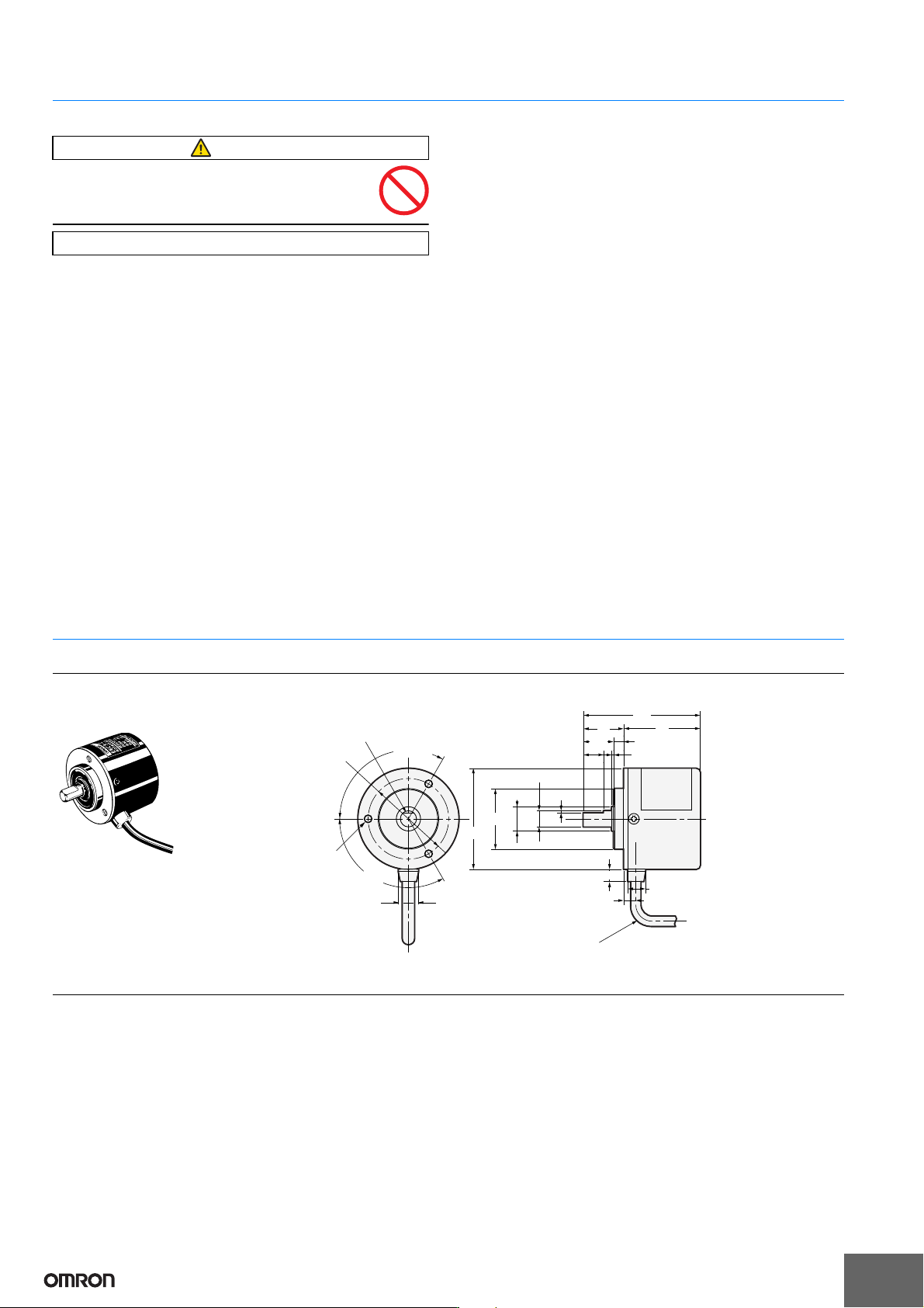
(Unit: mm)
Dimensions Tolerance class IT16 applies to dimensions in this datasheet unless otherwise specified.
Encoder
Accessories (Order Separately)
Servo Mounting Bracket
E69-2
Refer to Accessories for details.
WARNING
Precautions for Correct Use
E6C3-CWZ@@H
6
8.8
6
12 dia.
50 dia.
1
1
5
10
10
(15)
38
20
(58)
120
˚±0.1
120
˚±0.1
40
±0.1 dia.
30
+0
-0.021
dia.
8
+0
-0.018
dia.
5-dia. oil-resistant PVC-insulated shielded cable with 5
conductors (line driver: 8 conductors) (Conductor cross section:
0.2 mm
2
, Insulator diameter: 1.1 mm), Standard length: 1 m
Cut face D: Phase Z position (±15˚)
Three, M4
holes;
Depth: 5 mm
The E69-C08B Coupling is sold separately.
Couplings
E69-C08B
E69-C68B
Flanges
E69-FCA03
E69-FCA04