Hot-Bump-Pull-Application-Note.pdf - 第3页
Application Note Hot Bump Pull/Hot Pin Pull T emperature-time profile in Paragon ™ T est results in Paragon ™ T1 is the preheat region, this is selected by dening the temperature to reach and the time to achieve this hea…
Hot Bump Pull/Hot Pin Pull Application Note
What is Hot Bump Pull?
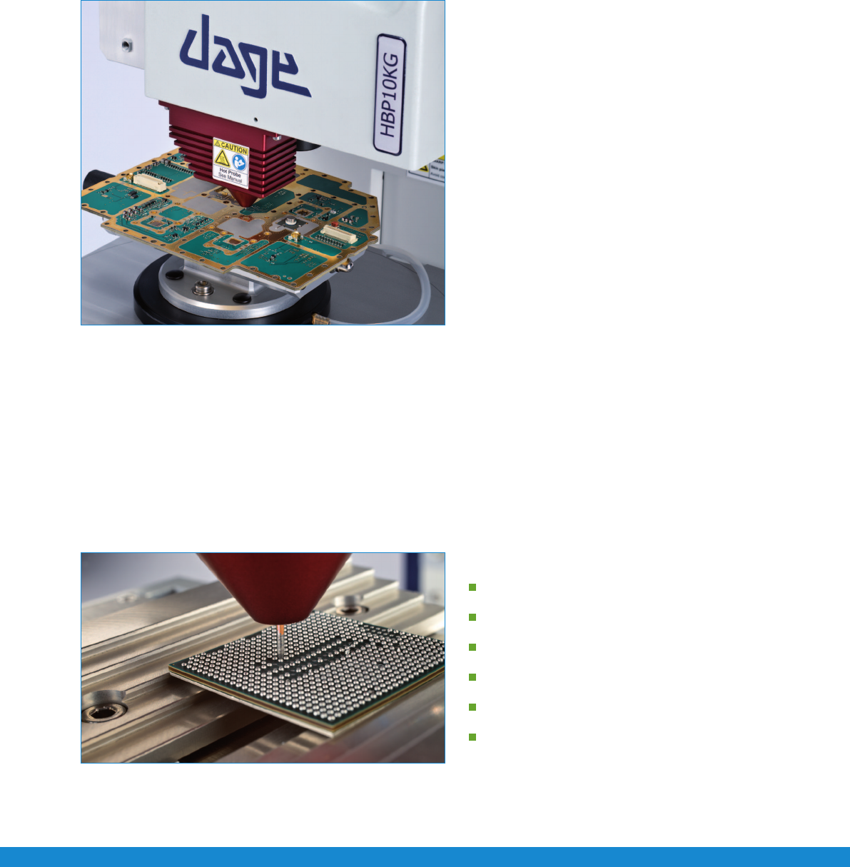
Hot Bump Pull load cartridge
e new Nordson DAGE 4000Plus HBP system is a totally
industry unique solution, conforming to IPC-9708 as well
as JEITA ET-7407A. It is fully integrated into a single load
cartridge on a standard 4000Plus system. Heating, cooling
stages and pin clamping mechanism are integrated into the
single load cartridge. e Paragon
™ software provides a user
friendly interface via temperature time proles to setup a test.
e new cartridge design allow simple straight test pins to
be used, allowing maximum force to be transferred as well as
providing a low cost consumable for testing. e new straight
pin design provides successful and consistent testing.
It is important to pull the pin vertically, directly by the
apparatus without imposing any bending moments.
e latest pad cratering standard, IPC-9708, denes hot bump pull as a method to evaluate the susceptibility of
printed board assembly materials and designs to cohesive dielectric failure underneath surface mount technology
attach pads. A method that can be used to rank order and compare dierent materials and parameters.
The Hot Bump Pull Test Procedure
e test procedure consists of two parts, set up of the test parameters and positioning of the pin over a solder bump.
Firstatemperatureproleiscreated,thisallowsausertoinputtemperatureandtimecriteriaforreowandtestconditions.
is simple interface only requires the desired temperature and the time to reach that temperature. e heating and cooling rates
as well as test execution are then automatically handled by the hardware and software.
A temperature time prole consists of the following stages.
Preheat
Soak
Rate of rise
Reflow/Liquidus
Cool down
Test execution
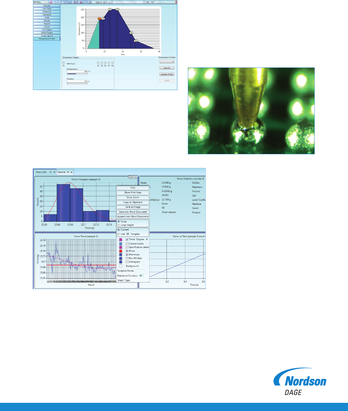
Close up of copper probe on BGA
Application Note Hot Bump Pull/Hot Pin Pull
Temperature-time profile in Paragon™
Test results in Paragon™
T1 is the preheat region, this is selected by dening the
temperature to reach and the time to achieve this heating period.
T1 to T2 is the soak period, the soak time can be selected.
T2 to T3 is the rate of rise.
A straight pin is vertically inserted into the cartridge, where it is held in place. e pin is then lowered onto the solder bump via motorised
horizontal and vertical stages. e pin is set so that it is touching the solder bump. e test is then executed, where the pin temperature
rampsupaccordingtothedenedtemperatureprolecreated.Atreowpointthepindropsdowntoadesiredlevel,ensuringagood
solder joint. e clamping mechanism then engages and clamps the pin so it is ready to be pulled. e cooling is handled internally by
pulsing compressed air past the pin and onto the test sample, cooling at the dened temperature prole.
Once the test temperature is reached, the test is automatically executed, recording the force-time,
force-distance and energy values.
T3toT4isthereowperiod,thereow
time period can be selected.
T4 to T5 is the cooling period.
T6 is the temperature where the test will be executed.
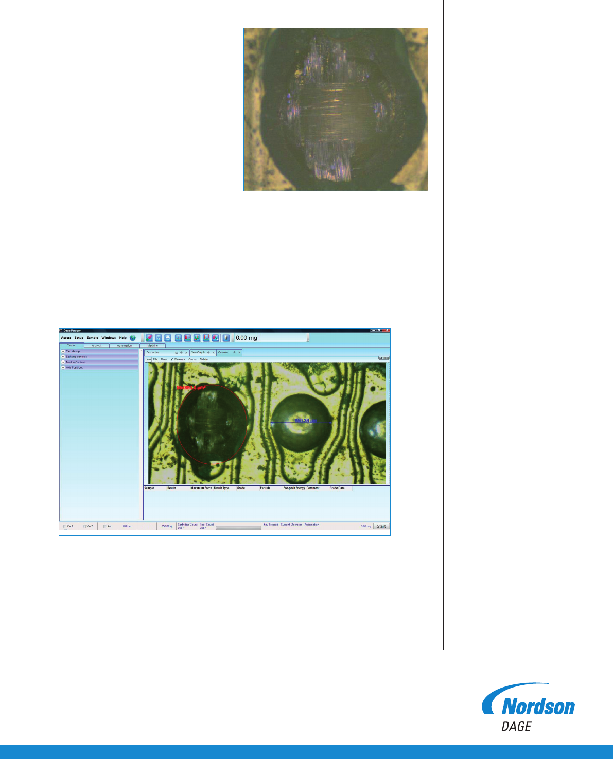
Close up of solder ball reflow
Hot Bump Pull/Hot Pin Pull Application Note
Nordson DAGE
25 Faraday Road
Rabans Lane Industrial Area
Aylesbury, Buckinghamshire HP19 8RY, UK
For more information,
please contact your
Nordson DAGE regional office
or speak with your
Nordson DAGE representative,
all of which are listed on
www.nordsondage.com.
Americas
+1 510 683 3930 Phone
sales@nordsondage.com Email
China
+86 512 6665 2008 Phone
sales.ch@nordsondage.com Email
Germany
+49 7021 950690 Phone
sales.de@nordsondage.com Email
Japan
+81 432 995851 Phone
sales.jp@nordsondage.com Email
South East Asia
+65 655 27533 Phone
sales.sg@nordsondage.com Email
United Kingdom
+44 1296 317800 Phone
globalsales@nordsondage.com Email
+44(0)1296 317800 Copyright © Nordson DAGE
www.nordsondage.com AN-BT-HBP-050411
Failure mode inspection
Conducting a HBP test and producing a failure
mode is one part of the test. e other
is to capture the visual data and be able to store
it in a convenient manner, not slowing down
the testing operation.
e 4000Plus has the capability to take detailed
images in between tests. is is achieved via
the optional built in image capture camera.
e camera can be set up to take a high
resolution image of the area under test and
store it for analysis or reporting.
e test operator can also allocate appropriate
failure modes via a user friendly GUI, which is
important for failure analysis. Reports can be
generated where force, data, failure mode and
image can be presented.
Failure mode image capture via integrated camera
Image analysis within Paragon
TM