ALD8700S-Brochure_2022.pdf - 第4页
Funct iona l specifica tion Inspection method Camera Lighting system Program creation Operation system Inspection board specification Inspe ction pe rform ance Resolution Height measurement range Speed FOV size Inspection…
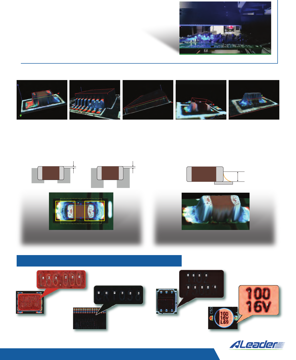
High-range, precise, shadow-free 3D height measurement of solder joints and
components coupled with simultaneous high-resolution, high-quality 2D images.
100% board coverage including the smallest parts.
Unique optical system developed by ALeader
delivers an accurate, reliable 3D measurement
without compromising 2D image quality
• 4-direction structured light (developed in-house,
advanced phase-shifting digital projection system)
• Multi-directional (360˚ horizontal, 0-90˚ vertical)
LED illumination system
• High-speed telecentric camera
Inspection pass-fail criteria complies with IPC-610 standard for shift and solder
fillet measurement
Tolerances defined according to IPC level (dependent of pad size)
Best-in-industry component marking recognition
Open Short
Pads defined by PCB Gerber Solder fillet height measurement
BGA lifted Wrong height Billboard
Beyond Innovation
Inspection result verification
Process control
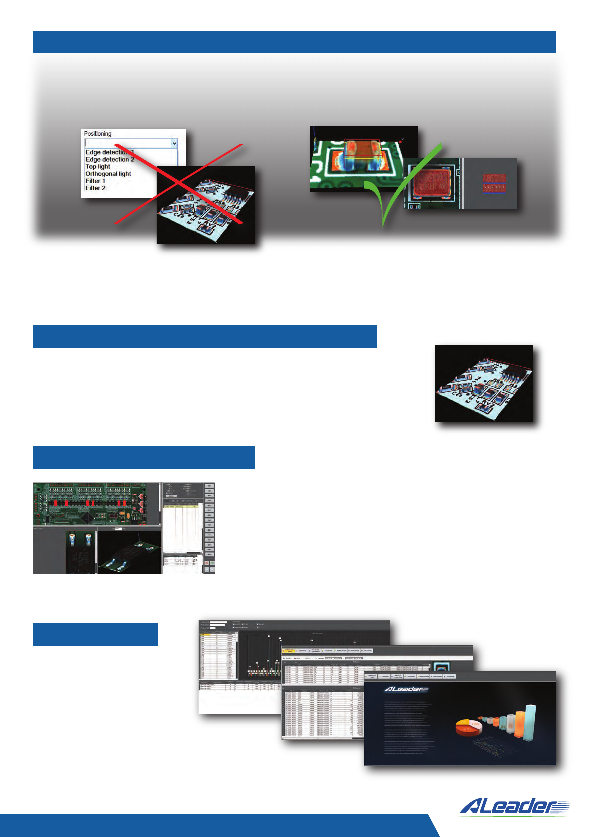
Easy programming. Friendly and intuitive user interface.
Insensitivity to the Component’s and PCB Color
•
Visualized and transparent definitions, no “black box”, no “special” algorithms
•
Defect samples are not required for creating a program without escapes
•
AI based auto-programming
•
Central library with part number and package links
• Simple and fast definition of non-standard
components
• Over 90% of the program can be done offline
• One-click solution for OCV/OCR and body
color definition
• Easy setup of skipped components
• Effective debugging procedures
• Ensures the operator will not miss the defect detected by AOI
• Easy to find component location on the PCB
• Clear component top and 3D interactive image for
reliable verification
• A real board is not required for decision making
• Inspection history review
• Operator feedback
• Possibility to use one repair station for multiple AOI machines
ALeader’s AOI is capable of inspecting PCBs of any color.
No user adjustments are required during program creation and
tuning. The color of the component does not reduce the system’s
accuracy; however it serves wrong component and polarity
detection, as well as other inspections.
• Real-time SPC charts
• History review and analysis
• Cp, Cpk, GR&R
• Traceability
• Reports
Beyond Innovation
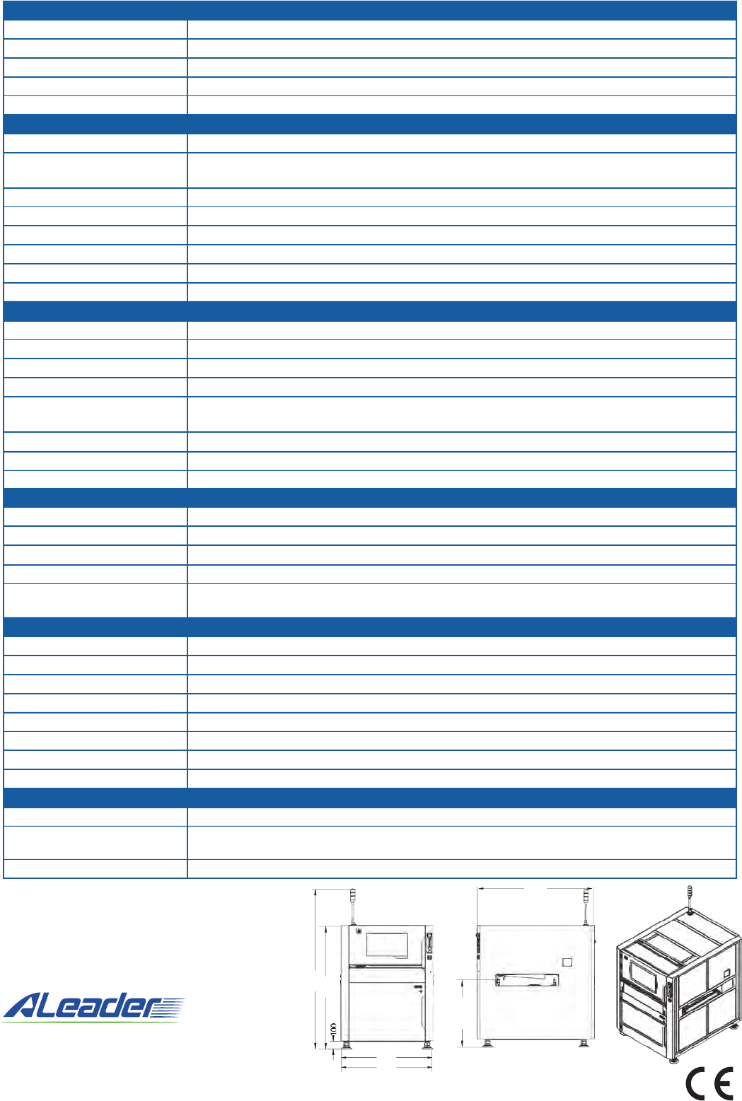
Functional specification
Inspection method
Camera
Lighting system
Program creation
Operation system
Inspection board specification
Inspection performance
Resolution
Height measurement range
Speed
FOV size
Inspection coverage
Component color
OCV/OCR
IPC compatibility
All colors and all pad finishes
Min 50mm x 50mm, Max 450mm x 500mm (ALD8710S) 650mm x 710mm (ALD8730S)
1500mm x 450mm (ALD8750S) 450 x 330/610mm (ALD8710D) 650mm x 330/610mm (ALD8730D)
0.2mm to 7mm
Up to 3kg
+/- 5mm
Top 2.5mm, Bottom 3mm
50/40 mm (ALD8710S, ALD8730S), 65/40 mm (ALD8750S), 40/40 mm (ALD8710D, ALD8730D)
03015 (metric), 0.3mm pitch
Top - 14µ (10µ, 7µ - option), Height – 0.7µ
upto 20mm
Less than 600ms/FOV
56.00 x 42.00 mm (14µ), 40.96 x 30.72 mm (10µ), 28.67 x 21.50 mm (7µ)
Missing, misalignment, billboard, up-side-down, tombstone, damaged, wrong component, lifted leads,
open, insufficient/excessive solder, shorts, polarity, solder balls, foreign object, etc...
Component color and transparency doesn’t affect performance, but used for wrong part inspection
Standard on each machine
Offset (pads defined by Gerber or bare board scan), solder fillet - height measurement
Features and options
Special features
Barcode system
Server mode
Remote control
Additional options
Supports auto-change programs, multi-boards (include bad mark) and multiprogram inspection modes
Auto-read barcode with camera - 1D and 2D; External reader scans back side barcode (option)
Central server, multiple machines data handling
Remote control through TCPIP for verification, system operation and program adjustment
SPC, repair station, offline programming station, external barcode scanner, support pins
Support applications - Site Dashboard, First Article Inspection, Package Link
Hardware
Conveyor
Conveyor direction/time
X/Y driver
Display
Power supply
Compressed air
Equipment communication
Operational conditions
Weight
Dimensions
Conveyor height
Dimension and Weight
920kg (ALD8720S), 1150kg (ALD8730S)
1000x1340x1610 (ALD8710S), 1000x1540x1610 mm (ALD8710D), 1200x1540x1610mm (ALD8730S,
ALD8730D), 2100x1210x1550 mm (ALD8750S)870-970mm
880-950mm
Flat belt conveyor, automatic clamp (pneumatic), auto load and unload, automatic width adjustment
Left to Right or Right to Left, in\out time 4 sec
Screw and AC server driver. PCB fix, camera moves X/Y
23.6 inch, touch screen
AC230V 50/60Hz, <1.5 KVA
0.4-0.8 MPA
SMEMA
10-35˚C, 35~80% RH (no dew)
Phase Measurement Profilometry
12MPix high speed intelligent camera, telecentric lens
4-directional structured light digital projection, top and 360˚ steep color LED light
CAD and Gerber files import, Central Library, Part Number links, Auto Programming, Central Library
Windows 10 Professional (64 bit)
PCB type
PCB size
PCB thickness range
PCB weight
Maximum PCB warpage
Clamping system edge clearance
Bottom/top clearance
Min component size
1180
1610
2085
1200
880~950
1540
Beyond Innovation
ALeader Vision Technology Co., Ltd.
Manufacturing
Dongguan city, Guangdong province 523128, China
ALeader Europe Ltd.
International Marketing- Training Center - Support Center
Industrial Zone Netser Sereni 7039500, Israel
Tel: +972-89208844 Fax: +972-89207711 | www.aleader-europe.com
Above specificaons are subject to change without noce.
Images used in the brochure are for illustrave purposes only.
System footprint dimensions are shown for model ALD8730S.
For other models please refer to the specificaon table