TS1201-user-guide.pdf - 第3页
6 6 TROUBLESHOOTING PROBLEM POSSIBLE CAUSE CORRECTION Fluid leak at dispensing needle • Fluid pressure is too high • Pinch cushion damaged • Lower fluid pressure (60 psi or lower) • Replace pinch cushion Fluid leak from …
2
CONTENTS
Page Number
1. Introduction ……………………………………………………………3
2. Operating Instruction with Pressure Reservoir …………………………3
3. Operating Instructions with Gravity Feed Reservoir ………………...4
4. Typical Setup…,…………………………………………………………4
5. Pinch Tube Replacement………...…………….…….………..…………5
6. Troubleshooting …………………………………………………6
7. Spare Parts and Accessories ………………………………………7
8. Warranty ……………………………………………………………8
7
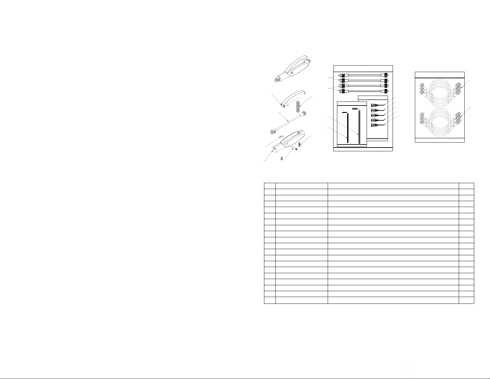
7 SPARE PARTS AND ACCESSORIES
17
16
5
4
2
7
10
9
1
2
8
3
12
15
14
13
11
15 TS25-1/2 BLUE TS NEEDLE, 400 SERIES, 25 GA. x 1/2", BLUE
TS NEEDLE, 400 SERIES, 22 GA. x 1/2", BLACK
TS NEEDLE, 400 SERIES, 21 GA. x 1/2", GREEN
TS NEEDLE, 400 SERIES, 20 GA. x 1/2", YELLOW
TS NEEDLE, 400 SERIES, 18 GA. x 1/2", PINK
HEX KEY, 3/32"
HEX KEY, 1/16"
SPRING, .250" I.D x .300" O.D x 1.25" LG.
SOCKET SETSCREW, #6-32 x 1/2" LG.
PIN, MODIFIED
BODY, DISPENSING GUN
PINCH CUSHION
PINCH TUBE ASSEMBLY, .098 BLACK
PINCH TUBE ASSEMBLY, .098
TRIGGER, HANDLE
5 1201-000-001
PART NUMBER
1201-000-004BK
1212-000-005
1201-000-004
1201-000-002
ITEM
2
1
3
4
TS21-1/2 GR
TS20-1/2 YEL
TSD1597-5
TS22-1/2 BLACK
TS18-1/2 PINK
TSD1150-7
TSD1123-15
1201-000-003
TSD1597-1
10
7
6
8
9
13
12
11
14
DESCRIPTION
BOX, 11-3/4 x 8-3/4 x 3 (NOT SHOWN)
FLUID LINE ASSEMBLY, BLACK
FLUID LINE ASSEMBLY
FOAM SET (NOT SHOWN)
TSD2107-1
TSD126-324
TSD126-324 BK
TSD2108-6
18
17
16
19
1
1
QTY
2
3
1
1
1
1
1
1
1
1
1
1
1
1
3
3
1

6
6 TROUBLESHOOTING
PROBLEM POSSIBLE CAUSE CORRECTION
Fluid leak at
dispensing
needle
• Fluid pressure is
too high
• Pinch cushion
damaged
• Lower fluid pressure (60
psi or lower)
• Replace pinch cushion
Fluid leak from
body
• Pinch Tube
ruptured
• Replace Pinch Tube
No fluid flow
• No fluid pressure
• Stroke adjustment
screw is in closed
position
• Fluid dry inside
Pinch tube
• Dispense tip
clogged
• Increase fluid pressure (1-
60 psi)
• Open stroke adjustment
screw
• Replac e new Pinch Tube
• Replace new Dispense tip
Fluid drool at
dispense tip
• Air entrapped in
fluid tubing
• Purge Pen to remove air
bubbles
3
1 INTRODUCTION
The TS1201 Pen is a basic pinch tube type valve. It has several unique features that
provide very broad areas of application.
1. The replaceable pinch tube assembly has male and female luer lock
fittings molded onto a polyethylene tube. The assembly is capable of
shutting off fluid pressure up to 60 psi.
2. The ON/OFF lever actuator provides precision control, capable of making
dots or continuous beads.
3. A stroke adjustment for the lever is built into the Pen body. This
adjustment makes the dispensing of small dots possible with a relatively
high degree of repeatable control.
4. A wide range of interchangeable fittings can be used to adapt supply hoses
from either gravity or pressurized supply reservoirs. The standard supply
hose provided with the Pen is a Polyethylene tube that can connects the
Pen directly to most reservoir.
2 OPERATING INSTRUCTIONS WITH PRESSURE RESERVOIR
1. Connect the fluid tubing from the material reservoir to the female fitting on the
Pen.
2. Hold the Pen in your hand as if you were writing. Depress the ON/OFF lever
and open the supply reservoir to feed the Pen. As soon as all air has been
purged from the supply hose and the pinch tube asembly, release the ON/OFF
lever to shut off the fluid flow.
3. Attach appropriate dispense needle to the male luer lock fitting of the pen
4. To fine tune the flow control or dot size, use the included allen wrench to adjust
the stroke of the ON/OFF lever. This adjustment is on the underside of the Pen
body, opposite from the lever.
5. The shot size can be adjusted by the following parameters:
a. Pressure on the supply reservoir
b. Dispense tip size
c. Stroke adjustment on the ON/OFF lever
6. Normally the pinch tube assembly will provide 100,000 to 200,000 cycles
before requiring replacement. When replacement is necessary, refer to detailed
instructions in Section 3. “PINCH TUBE ASSEMBLY REPLACEMENT”
4
3 OPERATING INSTRUCTIONS WITH GRAVITY FEED RESERVOIR
The viscosity of the fluid to be dispensed by gravity, or a combination of
gravity/siphon, must be low enough (1 to 800 cps).
A liquid tight seal must be made to the reservoir or supply source for gravity flow
applications. In some cases, a hole can be drilled in the cap of the bottle containing
the fluid. The hole should be small enough to provide a tight fit on the supply hose.
Once end of the suply hose should be cut off at a beveled angle and forced throught
the drilled hole until it reaches the bottom of the bottle. If the bottle is to be turned
upsided down, a vent hole must be punctured in the bottom of the bottle.
If gravity/siphoning is to be used from a plastic bottle, a vent hole must be made in
the cap of the bottle, To prime the Pen in the latter instance, close the vent hole with
a plug of cover with fingertip, depress the pen’s ON/OFF lever to open the tube and
squeeze the bottle to force the liquid throught the Pen. Once all air has been purged
from the supply line, remove the plug from the vent hole and proceed with
adjustments previously listed.
4 TYPICAL SETUP
Figure 1.0
5
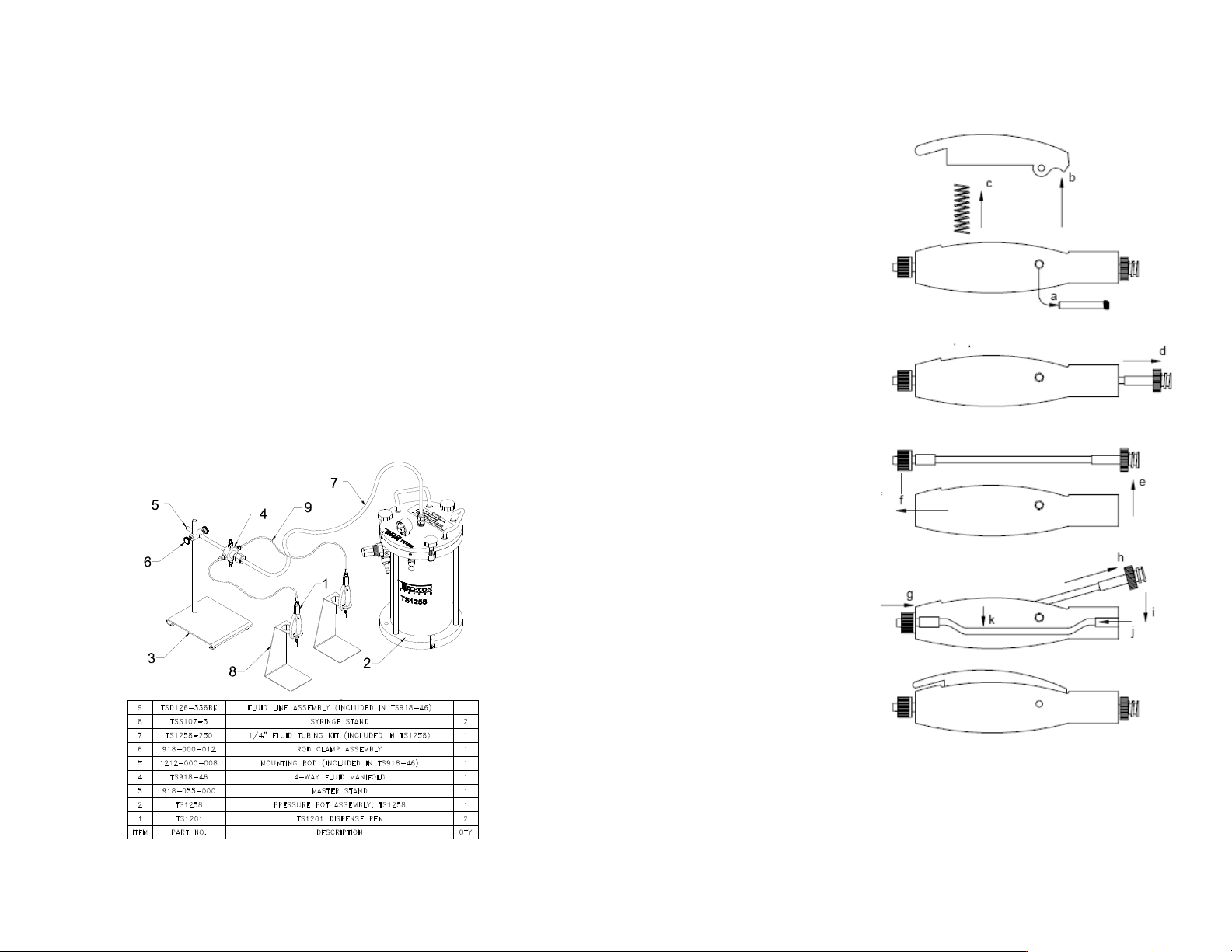
5 PINCH TUBE REPLACEMENT
1. Unscrew pivot Pin (a),
remove Trigger (b) and
Spring (c)
2. Pull one end of Pinch
Tube out (d) and
stretching it until fitting
clears body
3. Now pull stretch end of
Pinch Tube up (e).
Then pull out the
opposite end (f) to
remove
4. To repl ace new Pinch
tube, insert fitting of
Pinch Tube in one end
of the body until fitting
clears (h)
5. Now pull Pinch Tube
down (i) and insert the
female fitting into the
body (j). Finally, secure
by pushing Pinch tube
to the bottom inside of
body (k) and reassemble