TS910-user-guide.pdf - 第4页
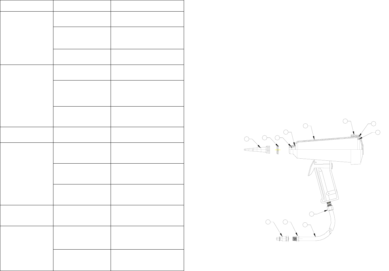
4 3. TROUBLE SHOOTING PROBLEM POSSIBLE CAUSE CORRECTION Excessive air pressure Reduce pressure to below 50 psi Dirt or foreign substance clogging poppet seal Clean poppet by blowing air Air leak at relief poppet Relief p…
2
CONTENTS
Page number
1. Specifications…………….……………………………………….3
2. Setup instructions ………….……………………………………3
3. Trouble shooting ….……………………………………………4
4. O-ring replacement ….……………………………………………5
5. Spare parts …………………..……………………………………6
6. Warranty ……………………………………………….7
7
10. LIMITED WARRANTY
Manufacturer warrants this product to the original purchaser for a period of
ninety (90) days from date of purchase to be free from defects in material and
workmanship, but not against damages by misuse, negligence, accident, faulty
installations and instructions. Manufacturer will repair or replace (at factory’s
option), free of charge, any component of the equipment thus found to be
defective, on return of the component “PREPAID” to the factory during the
warranty period. In no event shall any liability or obligation of the
Manufacturer arising from this warranty exceed the purchase price of the
equipment. This warranty is only valid if the defective product is returned as a
complete assembly without physical damage. The Manufacturer’s liability, as
stated herein, cannot be altered or enlarged except by a written statement
signed by an officer of the company. In no event shall the Manufacturer be
liable for consequential or incidental damages. A return authorization is
required from OK International prior to shipping a defective unit to the factory.
Manufacturer reserves the right to make engineering product modifications
without notice.
Send warranty returns to:
OK International
12151 Monarch Street
Garden Grove, Ca 92841
TSI-0071 Rev_A

6
No. Part number Description
1 910-TN Nozzle
2 910-25 Nozzle retaining nut
3 TSD1400-014A O-ring
4 910-3 Lock Ring
5 910-26 Body
6 910-2 Cap
7 910-8 Seal
8 910-13 Seal Retaining Ring
9 TSD923-1 Hose Barb Fitting
10 TSD1099-11 Air Hose, 5’
11 TSD922-1 Hose Fitting
12 TSD356-6 Air Connector
3
1. SPECIFICATIONS
Size: 7.5” (19.5 cm) x 6.5” (16.5 cm)
Weight: 0.60lb (0.27Kg)
Maximum pressure: 50.0 psi (3.44 bar)
Air inlet port: 1/8 NPT
Air hose length: 5.0’ (1.5 m)
2. SET UP INSTRUCTIONS
1. Assemble appropriate air connector fitting to end of air hose
assembly
2. Remove gun cap by rotating counterclockwise
3. Place Nozzle onto squeeze tube containing material to be
dispensed, make certain that nozzle is correctly and firmly
threaded onto squeeze tube
4. Place squeeze tube into gun assembly by inserting nozzle through
dispense end opening
5. Pull nozzle through opening until firmly seated then thread nozzle
retainer nut over nozzle. It may be necessary to hold the squeeze
tube to prevent rotation.
6. Install the gun cap back securely onto the gun assembly
7. Cut nozzle tip to desired dispensing orifice
8. Connect air hose assembly to air source
9. Turn up air pressure (50 psi max) and squeeze the gun trigger until
desired flow is achieved. Recommended starting pressure is 20
psi.
10. When dispensing process is completed, remove the gun cap
11. Hold the squeeze tube while removing nozzle retaining nut
4
3. TROUBLE SHOOTING
PROBLEM POSSIBLE CAUSE CORRECTION
Excessive air pressure
Reduce pressure to below 50
psi
Dirt or foreign
substance clogging
poppet seal
Clean poppet by blowing air
Air leak at relief
poppet
Relief poppet damaged Return gun for repair
Cap not firmly seated Re-install cap
Dirt or foreign
substance interfering
with gasket seal
Clean gasket
Air leak at gun cap
assembly
Defective gasket Replace with new gasket
Air leak at trigger Trigger damage Replace new trigger
Air pressure is too low Turn up air pressure
Nozzle not cut Cut nozzle
Material does not
dispense
Trigger damaged Replace trigger
Material dispenses
erratically, “Spitting”,
“Popping”
Nozzle cross threaded
or not threaded down
firmly
Re-install nozzle correctly
Tube was deformed at
front end when
threading on nozzle
Re-shape tube
Incomplete dispense
(Tube collapses at
front end, blocking
material
Too much air pressure
or too rapid dispense
rate
Reduce air pressure or reduce
dispense orifice
5
4. O-RING REPLACEMENT
Refer to figure 1.0
1. Disconnect air pressure
2. Using a screwdriver push the lock ring (4) and O-ring (3) out of the nose of
the gun assembly housing
3. Drop new O-ring into large end of gun
4. Push O-ring into nose of gun using soft tipped probe
5. Place lock ring over nozzle and squeeze tube then insert it onto nose of gun
6. Pull nozzle firmly through orifice to ensure complete seating of lock ring
5. SPARE PARTS
Figure 1.0
3
1
2
4
5
6
8
7
12 11
10
9