5989-5509.pdf - 第4页
Page 4 Find us at www .keysight.com T ake a Cl oser L ook SHIFT key and one-stop function keys for easy access Br oad range of measur ement functions, including temperatur e and capacitance Built-in battery charging for …

Page 3
Find us at www.keysight.com
Find Problems Quickly
Troubleshooting can be tricky, especially when you’re dealing with elusive problems. With the U1250
Series’data logging capability, you can ensure that every reading gets recorded manually or at intervals
you specify. Better yet: you can have virtually unlimited data logging saves when you connect any of the
U1250 Series DMM to a PC with the optional IR-to-USB cable.
In addition, the U1250 Series lets you achieve greater confidence in your measurements with accurate
true-RMS AC measurements, low DCV error rate of up to 0.025% and high-resolution display of
50,000 counts.
Uncompromising Ruggedness and Safety
The U1250 Series DMMs are housed in robust overmold enclosures, rated at CAT III 1000 V
and CAT IV 600 V and operate over a wide temperature range of –20 °C to +55 °C. Each DMM also
include a 30 kA high energy fuse to further protect you against violent fuse failures during high-current
measurements. Built tough and certified to stringent industrial standards, the U1250 DMM is what you
need to face the demands of everyday tasks.
Page 4
Find us at www.keysight.com
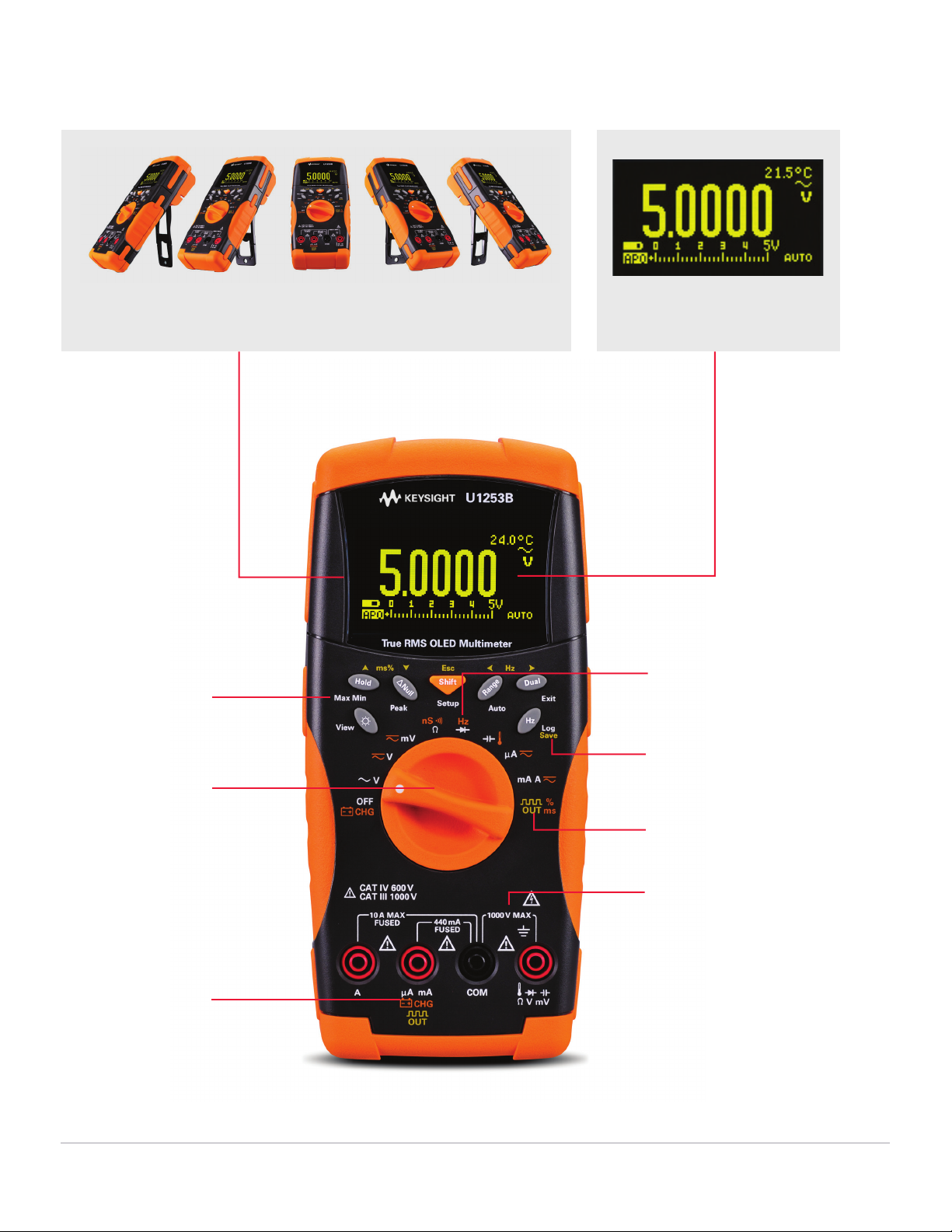
Take a Closer Look
SHIFT key and one-stop
function keys for easy
access
Broad range of
measurement
functions, including
temperature and
capacitance
Built-in battery
charging for
optimum capacitance
20 MHz frequency
counter
2
Data logging to internal
or external memory
Programmable square-wave
generator for stimulation of
digital circuits
2
CAT III 1000 V and
CAT IV 600 V overvoltage
protection for assurance
of your safety while you
go about your task
OLED display with approximately 160° viewing angle, and high contrast ratio
of 2000:1 for crystal-clear viewing
1
50,000 count dual display with
true-RMS reading capability
1
. U
1
253B on
ly
2. U1252B/U1253B only
5
3B on
ly
(Note: OLED is made of organic materials and it has its lifespan.)
Page 5
Find us at www.keysight.com
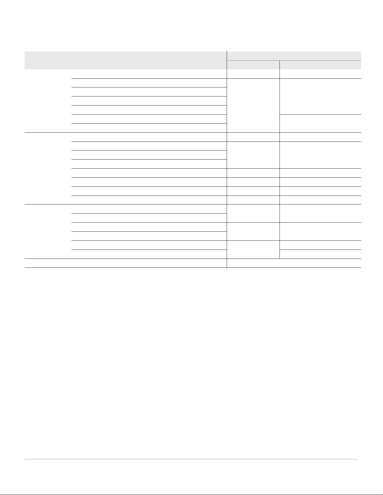
DC Specifications
1. Input impedance: Refer to Table A on page 10.
2. The accuracy could be improve to 0.05%+10 for U1251B or 0.05%+5 for U1252B and U1253B by using the Null function to zero out the thermal effect before measuring the signal.
3. These specifications are defined for 2-wire ohms using Math Null. Without Math Null, add 0.2 ohm additional error.
4. Maximum open voltage: < +4.2 V
5. The accuracy of 500 Ω and 5 kΩ is specified after NULL function, which is used to subtract the test lead resistance and the thermal effect.
6. For the range of 50 MΩ and 500 MΩ, the R.H. is specified for <60%.
7. The accuracy is specified for <50 nS and after NULL function with open test lead.
8. Always use the NULL function to zero out thermal effect with open test lead before measuring the signal. If the NULL function is not used, an additional 20 counts needs to be added to the DC
current accuracy. Thermal effect could occur due to the following:
– Wrong operation to measure the high voltage of 50 V ~ 1000 V for resistance, diode, and mV measurements.
– After battery-charging has completed.
– After measuring a current greater than 440 mA, it is suggested that the meter be left to cool down for twice the measuring time used.
9. Current can be measured up to 10 A continuously. An additional 0.5% needs to be added to the specified accuracy if the signal measured is in the range of 10 A~20 A for 30 seconds
maximum. After measuring a current of > 10 A, leave the meter to cool down for twice the measuring time used before application of low current measurement.
Function Range Resolution Test current/
burden voltage
Accuracy ± (% of reading + no. of least significant digit)
U1251B U1252B/U1253B
Voltage
1
50.000 mV 0.001 mV – 0.05 + 50
2
0.05 + 50
2
500.00 mV 0.01 mV – 0.03 + 5 0.025 + 5
1000.0 mV 0.1 mV –
5.0000 V 0.0001 V –
50.000 V 0.001 V –
500.00 V 0.01 V – 0.03 + 5
1000.0 V 0.1 V –
Resistance
3
500.00 Ω
5
0.01 Ω 1.04 mA 0.08 +10 0.05 + 10
5.0000 kΩ
5
0.0001 kΩ 416 µA 0.08 + 5 0.05 + 5
50.000 kΩ 0.001 kΩ 41.2 µA
500.00 kΩ 0.01 kΩ 4.12 µA
5.0000 MΩ 0.0001 MΩ 375 nA 0.2 + 5 0.15 +5
50.000 MΩ
6
0.001 MΩ 187 nA 1 + 10 1 + 5
500.00 MΩ
6
0.01 MΩ 187 nA N/A 3+10 < 200 MΩ / 8+10 > 200 MΩ
500.00 nS
7
0.01 nS 187 nA 1 + 20 1 + 10
Current 500.00 µA 0.01 µA 0.06 V (100 Ω) 0.1 + 5
8
0.05 + 5
8
5000.0 µA 0.1 µ A 0.6 V (100 Ω)
50.000 mA 0.001 mA 0.09 V (1 Ω) 0.2 + 5
8
0.15 + 5
8
440.00 mA 0.01 mA 0.9 V (1 Ω)
5.0000 A 0.0001 A 0.2 V (0.01 Ω) 0.3 + 10 0.3 + 10
10.000 A
9
0.001 A 0.4 V (0.01 Ω) 0.3 + 5
Diode test
8
– 0.1 mV 1.04 mA 0.05 + 5