MX3000 Brochure EN.pdf - 第6页
www .nordson.c om/T estInspec t Nordson T est & Inspection Japan ti-sales-jp@nordson.com Nordson T est & Inspection Sing apore ti-sales-eu@nordson.com Nordson T est & Inspection T aiwan ti-sales-tw@nordson. c…
6 | MX3000 Automated Final Vision Inspection MX3000 Automated Final Vision Inspection | 7
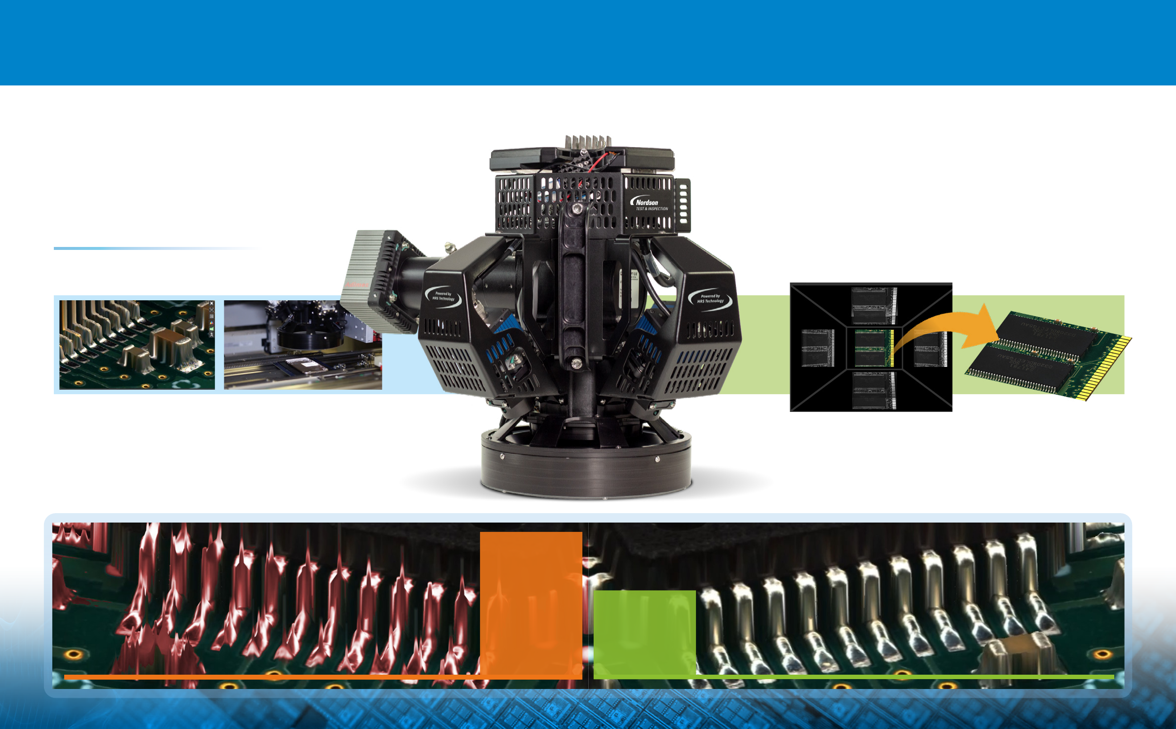
MX3000™ oers unmatched accuracy with the
revolutionary MRS technology by meticulously
identifying and rejecting reflections caused
by shiny components and reflective solder joints.
Reflection based distortions
MRS is designed to Inhibit reflection-based distortions
from shiny and specular surfaces.
Enabling the highest possible inspection accuracy at production speeds.
Multi-Reflection Suppression®
Without MRS
(MRS®) Sensor Technology
Eective suppression of multiple reflections is critical
for highly accurate measurements making MRS an ideal
technology solution for a wide range of applications
including those with very high quality requirements.
With
MRS
Without
MRS
8 | MX3000 Automated Final Vision Inspection MX3000 Automated Final Vision Inspection | 9
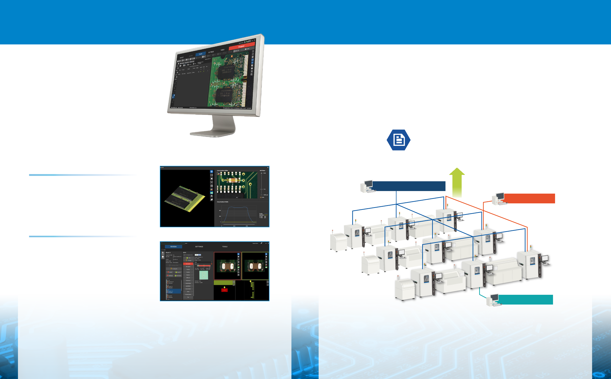
CyberReport™ oers full-fledged machine-level to factory-level SPC capability
with powerful historical analysis and reporting tools delivering complete
traceability for process verification and yield improvement. CyberReport™ is
easy to setup and simple to use while providing fast charting with a compact
database size.
Fast, Scalable SPC Solution
Factory-level SPC
Line-level SPC
Machine-level SPC
Yield
CYBERREPORT
SPISOFTWARE
AOISOFTWARE
CYBERREPORT
CYBERCMM
SPISOFTWARE
AOISOFTWARE
CYBERCMM
CYBER
PRINTOPTIMIZER
CYBER
PRINTOPTIMIZER
Intuitive, Easy-to-Use Soware
The MX3000™ soware is a powerful
yet extremely simple design with
an intuitive interface that reduces
training eorts and minimizes
operator interaction – saving time
and cost. The soware includes
multi-touch controls and 3D image
visualization tools, taking ease-of-
use to a whole new level.
Faster, Smarter Programming
With ultra-fast programming capabilities, auto
tuning and other enhancements, Nordsons’ AOI
soware significantly speeds set-up, simplifies the
process, reduces training eorts and minimizes
operator interaction.
AI
AI
2
(Autonomous Image Interpretation)
technology is all about keeping it simple -
no parameters to adjust or algorithms to tune.
And, you don’t need to anticipate defects or pre-
define variance either - AI
2
does it all for you.
With AI
2
, you have the power to inspect the
most comprehensive list of features and identify
the widest variety of defects. AI
2
oers precise
discrimination with just one panel inspection
making it a perfect solution for high-mix and
high-volume applications.
www.nordson.com/TestInspect
Nordson Test & Inspection Japan
ti-sales-jp@nordson.com
Nordson Test & Inspection Singapore
ti-sales-eu@nordson.com
Nordson Test & Inspection Taiwan
ti-sales-tw@nordson.com
Nordson Test & Inspection Korea
ti-sales-korea@nordson.com
BR-MX3000 20/01/2023-V1
For more information, speak with your
Nordson representative or contact your
Nordson regional oice
Nordson Test & Inspection
Europe, SEA, Africa
ti-sales-eu@nordson.com
Nordson Test & Inspection Americas
ti-sales-us@nordson.com
Nordson Test & Inspection China
ti-sales-cn@nordson.com
Specifications subject to change without prior notice.
Copyright © Nordson 2024. Other products and company
names mentioned are trademarks or trade names of their
respective companies.
Nordson Test & Inspection products are patent protected
and covered by the patent listed at www.nordson.com.
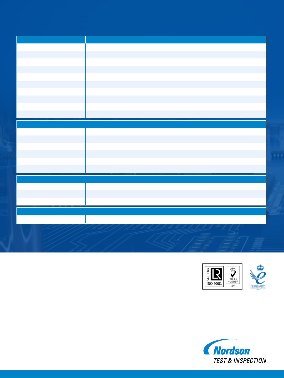
Inspection Capabilities
Inspection Speed 50 cm
2
/sec (2D+3D)
Minimum Component Size 0402 mm (01005 in.)
Board Length Min. 25 mm / Max. 140 mm
Board Width Min. 17 mm / Max. 35 mm
Component Height Clearance (max) 35mm
Component Types Inspected Standard SMT (chips, J-lead, gull-wing, BGA, etc.), through-hole, odd-form, clips, connectors, header pins, and more
Solder Joint Defects Categories Solder bridge, opens, lied leads, wettability, excess and insuicient solder, debris, and more
M3D Measurement inspection Lied lead, package coplanarity, polarity dimple and chamfer identification
Other Items Detected Gold-finger contamination, pin-in-hole, bent pins, debris, OCR/OCV and many others
Component Measurement Categories Component X, Y position and Rotation
Vision System
Imagers Multi-3D sensors
Image Transfer Protocol PCIe
Resolution Sub 10 μm
Image Processing Autonomous Image Interpretation (AI²) Technology, coplanarity and lead measurement
Programming Simple inline or oline
CAD Import Any column separated text file (Standard information required - ref designator, XY, Angle, Part no.,)
System Specifications
Power Requirements AC 220V, 3 phase, 60 Hz, 4 wire, Amp: 50A
System Dimensions 2.69m x 2.83m x 2.38 m (W x D x H)
Weight 4.0 tons
Options
SPC Soware, Alignment Target, Tray Loader/ Unloader Elevated Card, 2nd Review Station
Specifications