CrossoverGuide_Unimotor-fm.pdf - 第5页
Page 5 Application spec ics should be revie wed by an Emerson Application Enginee r . For additional a ssistance call 1 800 893 2321. Unimot or fm Ser vo Mo tors - E2/U2 migration t o E3/U3 models Motor Dimension Change…
Page 4
Application specics should be reviewed by an Emerson Application Engineer. For additional assistance call 1 800 893 2321.
Unimotor fm Servo Motors - E2/U2 migration to E3/U3 models
Order Code Changes
Unimotor fm frame sizes 075 mm, 095 mm, 115 mm, 142 mm
Use the following information as a guide to cross an existing Unimotor fm E2/U2 order code to the new E3/U3 order codes.
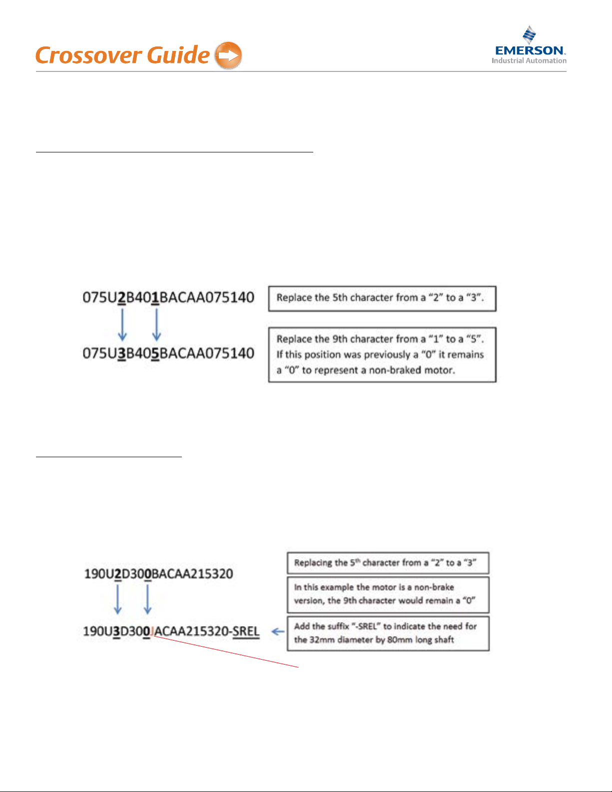
For motor frames 075, 095, 115 and 142 the new E3/U3 model string can be created simply by replacing the 5th character
from the left from a “2” to a “3”.
For motor models provided with a holding brake, identified with a “1” in the 9th character, the new holding brake order
code is now “5”.
Here is an example of these order code changes:
All other order code positions would remain the same when ordering a replacement motor in these frames.
Unimotor fm frame size 190 mm
For the 190 frame motor the same applies as shown for the 075-142 models. In addition to these changes a “-SREL” suffix
is required to indicate the required shaft length. The standard shaft on all Unimotor fm 190 E3/U3 frame lengths is now
32 mm diameter by 58 mm long. When replacing an existing Unimotor fm 190 E2/U2 model use the suffix “-SREL” on the
order string to indicate the 32 mm diameter by 80 mm long shaft dimensions associated with the E2/U2 models.
Here is an example of this order code change:
The “connection type” order code has changed from “B” to “J”.
This change has been only been made to the order code, the physical connector remains the same, size 1.5
Page 5
Application specics should be reviewed by an Emerson Application Engineer. For additional assistance call 1 800 893 2321.
Unimotor fm Servo Motors - E2/U2 migration to E3/U3 models
Motor Dimension Changes
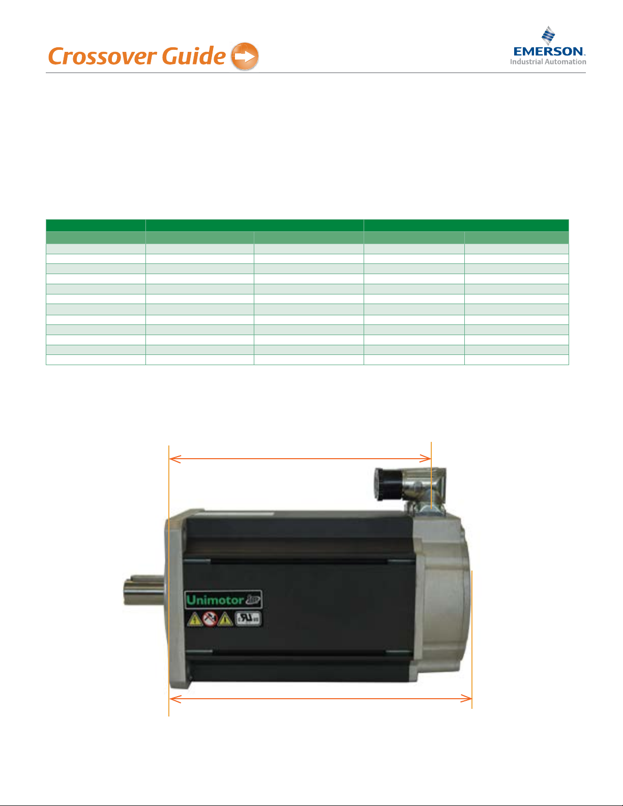
With the new E3/U3 models the motor length decreases on some of the frames. Along with this shorter motor length also
comes a difference in the connector position relative to the motor faceplate. With the shorter motor the cable connectors
move closer to the motor faceplate.
Connector Position and Motor Length Differences
Unimotor E3/U3 Connector Position Difference from U2/E2 (mm) Motor Length Difference from E2/U2 (mm)
Frame Non-Brake Braked Non-Brake Braked
075A-D 0 -15 0 -15
095A-E 0 -15 0 -15
115A-E -8.2 -23.2 1.4 -13.6
142A-E -25 -10 -33.4 -18.4
190 A -28.6 -19.4 -38 -28.6
190B -25.5 -16.4 -34.9 -25.8
190C -22.7 -13.3 -31.9 -22.7
190D -19.4 -10.3 -28.8 -19.7
190E -16.4 -7.2 -25.8 -16.6
190F -13.3 -4.2 -22.7 -13.6
190G -10.3 -1.1 -19.7 -10.5
190H -7.2 1.9 -16.6 -7.5
Differences to Note:
• With the shorter motor the cable connectors move closer to the motor faceplate
• Along with this shorter motor length also comes a difference in the connector position relative to the motor faceplate
Unimotor fm E3/U3
Connector Position
Motor Length
Page 6
Application specics should be reviewed by an Emerson Application Engineer. For additional assistance call 1 800 893 2321.
Unimotor fm Servo Motors - E2/U2 migration to E3/U3 models
Motor Parameters
Higher Torque ratings
The Cross Reference Table (page 3), shows in some cases that the stall torque of the E3/U3 models has increased. Although
this higher performance is available, it is not available to the application unless the servo drive has a sufficient current
rating and the appropriate drive parameters are set to the new motor data. Keep in mind that if the previous E2/U2 motor
was providing the required torque there is no need to change the existing drive settings, the new E3/U3 motor and existing
drive will provide the equivalent performance.
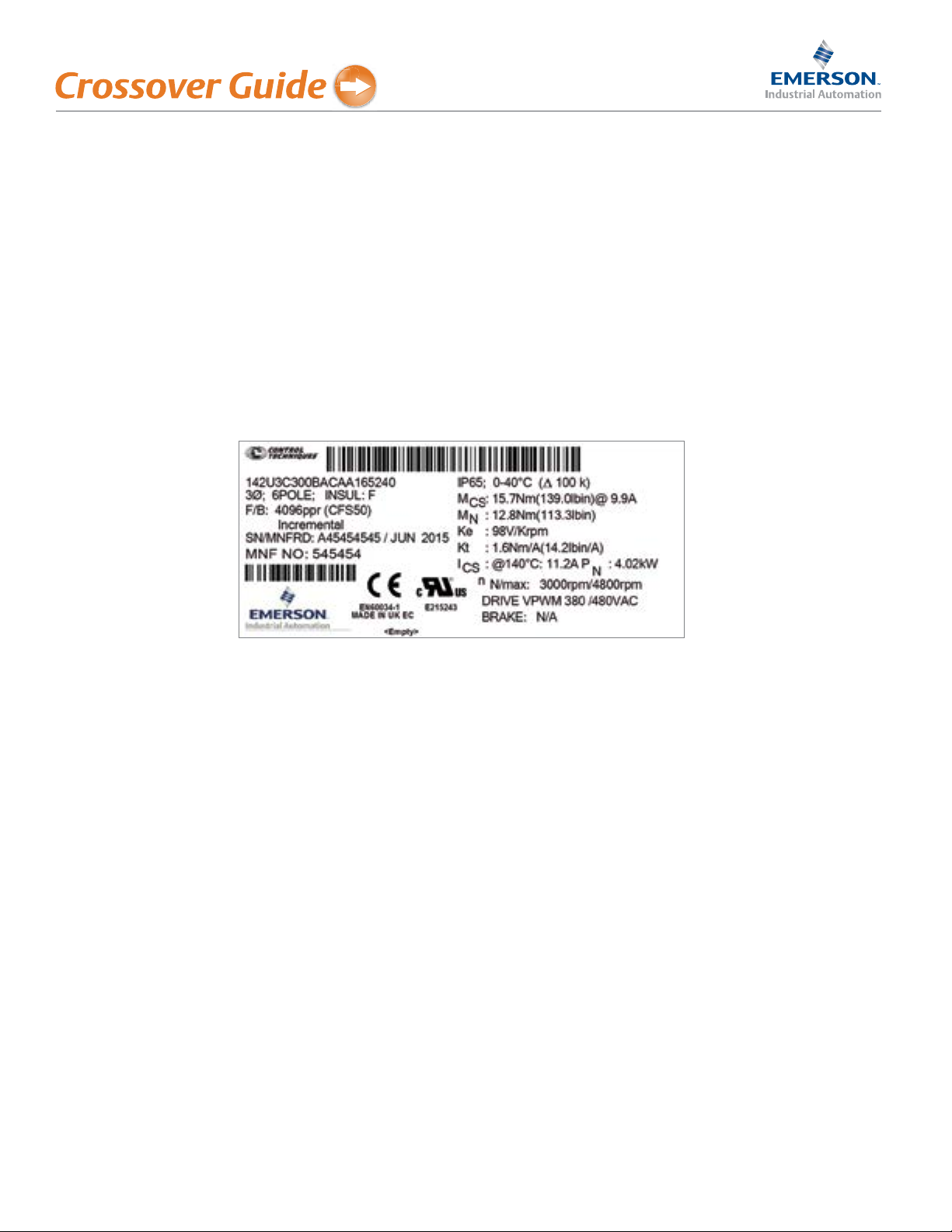
If the higher rating is needed use the motor name plate data to determine the information to enter for the new motor
parameters.
Use the following three steps to update the drives motor map information.
1. Use the appropriate commissioning software and update the motor information as indicated on the motor nameplate.
2. Verify that the motor feedback device settings in the drive match the motors feedback device.
3. Perform a rotating Autotune de-coupled from the load as described in the appropriate drive product literature.
4. Save the new drive parameters.