Nordson DAGE Die Strength Testing Application Note.pdf - 第4页
DS-AN-260619-V1 www .nordsondage.com For more inf ormation, speak with your Nordson represent ative or c ontact your Nordson re gional oic e Americas + 1 760 930 3307 sales@nordsondage. com Europe +44 1296 317800 global…
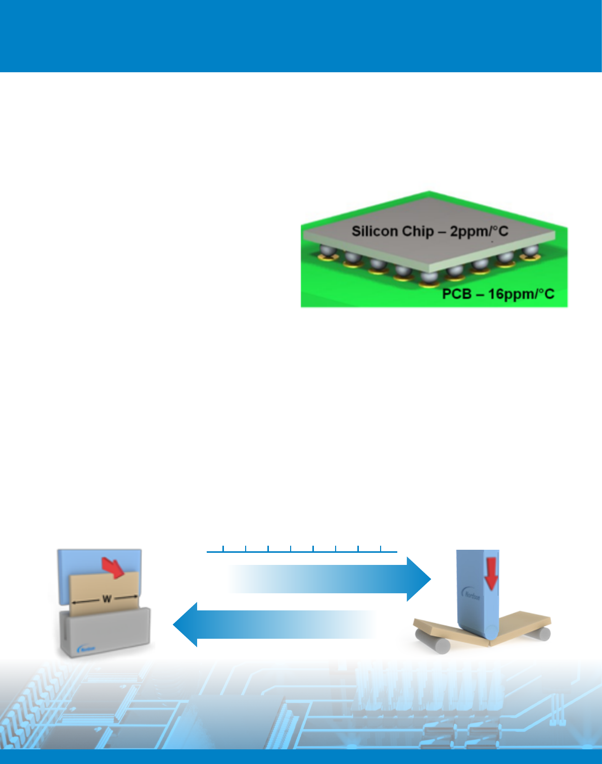
The challenge
The present trend for thin substrates and large area devices has made dies susceptible to fracture from small cracks
induced during dicing and thinning. Whether or not a die will fail depends on the applied stress and the size of any defects
present. There are several factors which require strength testing to be performed on individual die.
σ Inorganic semiconductors are brittle and their strength
is greatly affected by the presence of surface aws
such as chips and scratches
σ Die can experience high levels of stress due to CTE
mismatch or exure of the board they are mounted to.
σ Handling, back thinning and dicing processes all
introduce scratches into a die, so the question is not
‘are there defects on the die’, but ‘what effects do the
defects have on die strength?’
Flexural testing is ideal for assessing the impact of defects (cracks) and surface treatments on the strength of brittle
materials. As silicon dies are brittle, consistent set-up of the testing process is key to producing repeatable results. A good
test set-up for die strength testing needs to be:
1. Quick and repeatable test set-up
2. Repeatable and accurate micro tool positioning (both X and Y)
3. Easy to interpret results
It is important to correctly choose which test you should perform and this is generally done based on the thickness of the
die. For thicker die bend testing is recommended, while thin die the cantilever test can be used:
Die Strength Testing
Application Note
Figure 2 Bending loads can be caused by thermal expansion
Figure 1: Choosing the right test method
Die Thickness (μm)
10 20 30 40 50 60 70 80
3 Points Bending Method
Cantilever Bending Method
Die Strength Testing
Application Note
Die Strength Testing
Application Note
Three-point Bending
The conventional way of testing silicon die strength is the
three-point bend test; The die is pushed down by a roller
(or indenter) in the centre and supported at the sides.
For large samples, a PP50KG cartridge is available for
accurately measuring large bend loads. The three-point
bend apparatus can easily be converted to performing
four-point bend by replacing the single roller with a dual
roller assembly. Four-point bending generates a constant
bending stress between the two upper rollers, unlike
three-point bending, where the stress increases to a peak
under the centre roller. Four-point bending provides more
consistent results, but can only be carried out on relatively
long, thin components.
Nordson DAGE makes a range of support anvils to
provide a support span for a variety of die sizes, as the
ideal test has a large proportion of the die unsupported.
Small dies can be tested using the PP500G cartridge,
which is accurate down to 0.5 g force. The three-point
bend set-up meets SEMI G86-0303 and other applicable
international standards.
Support anvils can be custom made so that the die can
be simply slotted into place against a hard stop to ensure
quick and easy positioning every time. Where a variety of
die sizes needs to be tested, the die can be positioned
accurately using the nudge function of the bond tester
and then independently checked using the image capture
camera, to very high precision
Figure 4 Micro three-point bend set-up with self-aligning tool
Figure 5 Standard and customer options anvils for micro three-point bend
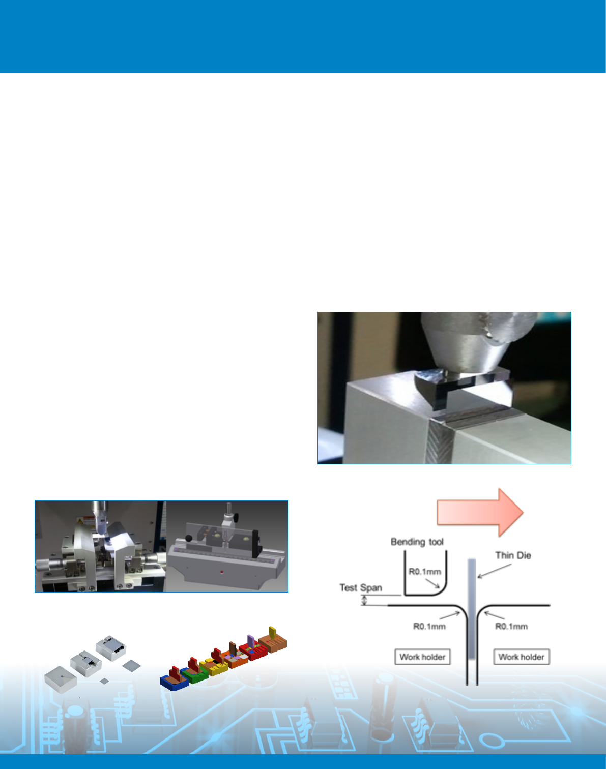
Cantilever Bend
When the die is very long and thin, the deection during a
three-point bend can cause the die to slip during the test,
invalidating the results. For these components, Nordson
DAGE bond testers can carry out cantilever bend tests.
The die is clamped into a support and the top is pushed
to bend the die. The bend test equipment is designed
to be compatible with common international standards,
including SEMI G96-1015. Cantilever bend allows the
bending span to be very short, eliminating the need to go
to very large deections. On Nordson DAGE bondtesters,
this small bending span is accurately controlled by using
the shear height function- consistent bending span is vital
to producing consistent test results.
Figure 7 A cantilever bend test
DS-AN-260619-V1
www.nordsondage.com
For more information,
speak with your Nordson
representative or contact
your Nordson regional oice
Americas
+ 1 760 930 3307
sales@nordsondage.com
Europe
+44 1296 317800
globalsales@nordsondage.com
China
+86 512 6665 2008
sales.ch@nordsondage.com
Germany
+49 89 2000 338 270
sales.de@nordsondage.com
Japan
+81 120 537 555
sales.jp@nordsondage.com
Korea
+82 31 462 9642
korea.at.cs@nordson.com
South East Asia
+65 6552 7533
sales.sg@nordsondage.com
Taiwan
+886 2 2902 1860
globalsales@nordsondage.com
United Kingdom
+44 1296 317800
globalsales@nordsondage.com
Die Strength Testing Application Note
Spherical bend
As the strength of silicon materials is
dominated by edge and surface aws, it is
sometimes necessary to test a die without
loading the edge. The solution is to use
a ball as the indenter and support the die
with a ring, so that the edges are outside
the loaded area.
Figure 8 Ball-on-ring bend testing
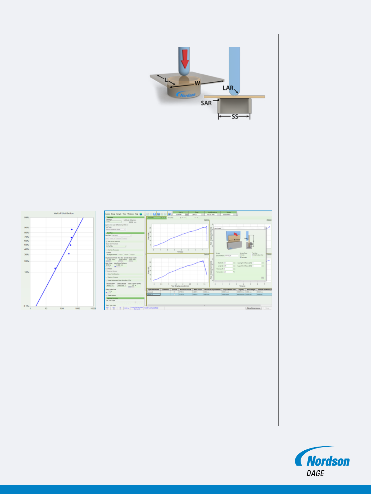
Analysis
A powerful way of understanding the data from testing brittle materials is through Weibull
analysis. Paragon™ software provides a Weibull plot as standard, eliminating the need to
carry out post-processing on the results. In addition, Paragon™ uses the sample dimensions
to allow the results to be plotted in terms of stress and strain, instead of simply load and
displacement, so that results can be compared with samples of different sizes.
Chose the right method for your die testing
Nordson DAGE supports all of the relevant test methods for die bend testing, no matter what
size of your die.
Figure 10 Paragon Materials™ die bend testing screen
Figure 9 Weibull distribtuion analysis