Nordson DAGE USB Connector Testing Application Note.pdf
In recent years USB connectors have become a standar d means of sharing both data and providing power to a variety of devices. Therefor e these connectors are r equired to be r obust and last reliably for long periods. S…
In recent years USB connectors have become a standard means of sharing both data and providing power to a
variety of devices. Therefore these connectors are required to be robust and last reliably for long periods.
Some connectors may suffer from wear due to repeated insertion and extraction, so it is important to know
how many cycles of insertion and withdrawal a USB connector design can sustain without a degradation in its
electrical or mechanical performance.
Cyclic loading not only provides useful information on connector lifetime, but is also a means of testing design changes,
such as pin shape, spring force, coatings and lubrication.
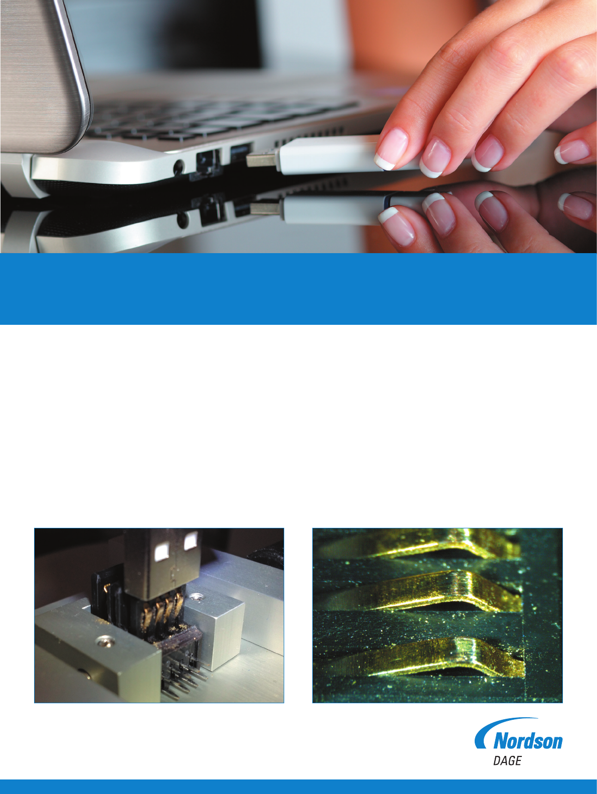
Complete connectors or individual pins can be tested, and electrical resistance measurements can be used to assess the
damage done by small repeated movements (fretting) see figure 1.
Figure 1: Test for fretting or test individual pins.
USB Connection Testing
Application Note

Contact Material Attributes
Tin
Low cost, few mating cycles,
susceptible to fretting corrosion
Hard gold
High resistance to corrosion, low insertion force,
high number of mating cycles
Silver Mainly used for high current contacts
Hard gold flashed
palladium-nickel
Particularly suitable for low signal levels, low wear,
high number of mating cycles
USB Connection Testing
Application Note
Understanding Connectors
There are several methods to test connectors:
σ Insertion Force – the maximum push force required to push the two halves of the connector together
σ Withdrawal Force – the maximum pull force required to pull the connector apart
σ Contact Resistance – the electrical resistance associated with the point of contact, typically around 10-30mΩ
σ Fretting – small rubbing movement between surfaces that are forced together.
σ Fretting Corrosion – oxidation of contacts due to fretting
σ Spring Constant – stiffness of the contact. Stiff contacts create high friction forces which can reduce fretting and
contact resistance but result in higher insertion and withdrawal forces
The optimum test method depends on the materials being used and their attributes.
Test Method
Nordson DAGE have worked with the Manufacturing Technology Centre (MTC) to develop bespoke tooling and test
methodology to characterize connector integrity and degradation through cyclic insertion and withdrawal testing.
The Nordson DAGE USB connector wear jig has a self-aligning function that minimizes the loads in the X and Y direction
while the USB connector is being moved in the Z direction. This jig can also be locked after the initial alignment to simulate
withdrawal processes where the connector is held rigidly.
USB Connection Testing
Application Note
Two Ways of Testing
The Nordson DAGE 4000Plus provides a flexible
testing platform, with Paragon
TM
Materials Software,
but sometimes a specialist or custom jig is needed
to support samples such as USB connectors.
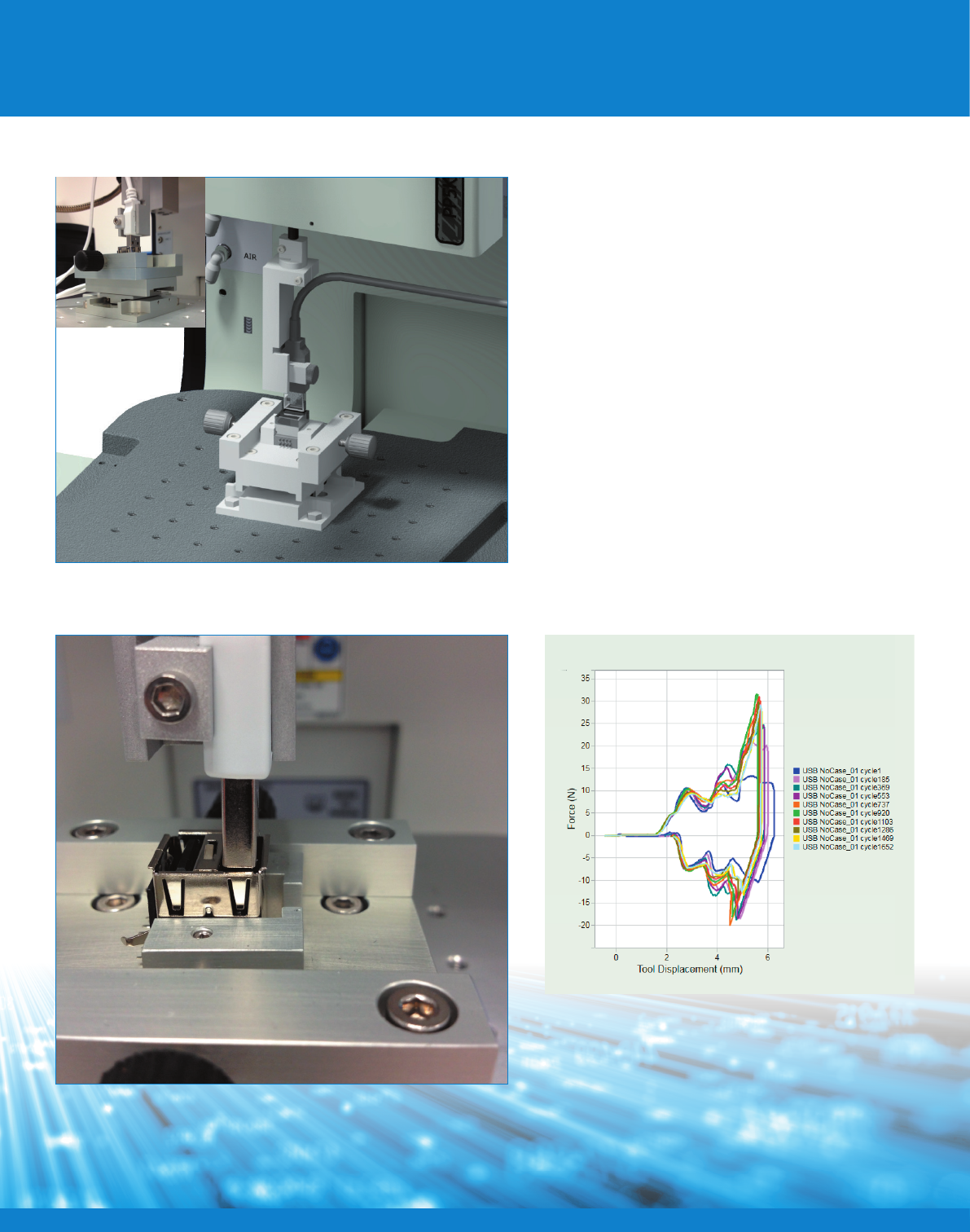
To measure the cyclic performance of a USB
design, the connector must be repeatedly inserted
and withdrawn from the mating connector, while
measuring the force of insertion and withdrawal to
understand its mechanical performance, as well as
measuring its electrical performance, such as pin
resistance, within the same experiment.
The instrument can interface with any 0-10 V
external measuring device, so a resistance meter
can be used to produce a resistance versus time
graph in real-time, during the experiment. Paragon
Materials Software can trigger the data capture
in external devices as well, for multi-channel data
capture devices.
Figure 2: USB self-aligning connector jig.
Figure 4: Paragon Materials software interface showing multiple
test cycles.
Figure 3: X, Y and Z axis control to < 1 micron for connector alignment.