A000056-full-pinout.pdf - 第7页
This work is licensed under the Creative Commons Attribution-ShareAlike 4.0 International License. To view a copy of this license, visit http:// creativecommons.org/licenses/ by-sa/4.0/ or send a letter to Creative Commo…
This work is licensed under
the Creative Commons
Attribution-ShareAlike 4.0
International License. To view a
copy of this license, visit http://
creativecommons.org/licenses/
by-sa/4.0/ or send a letter to
Creative Commons, PO Box 1866,
Mountain View, CA 94042, USA.
SKU code: A000056
Full Pinout - Page 6 of 8
Last update: 29 Jun, 2022
To check the maximum currents
applicable per pins please
see the documentation on
DOCS.ARDUINO.CC/HARDWARE/DUE
The ADC’s channel 15 is not
available because connected to
the ATSAM3X8E temperature sensor
CIPO/COPI have previously been
referred to as MISO/MOSI
MAXIMUM current per
I/O lines is 130mA
Legend:
Power Power Input
Power Output
Ground
GPIO Digital External
Analog External
Main Part
Secondary Part
Internal Component
Other Pins (Reset, System
Control, Debugging)
I2C Default
SPI Default
UART/USART Default
Other SERIAL Communication
Analog Default
PWM/Timer
LED
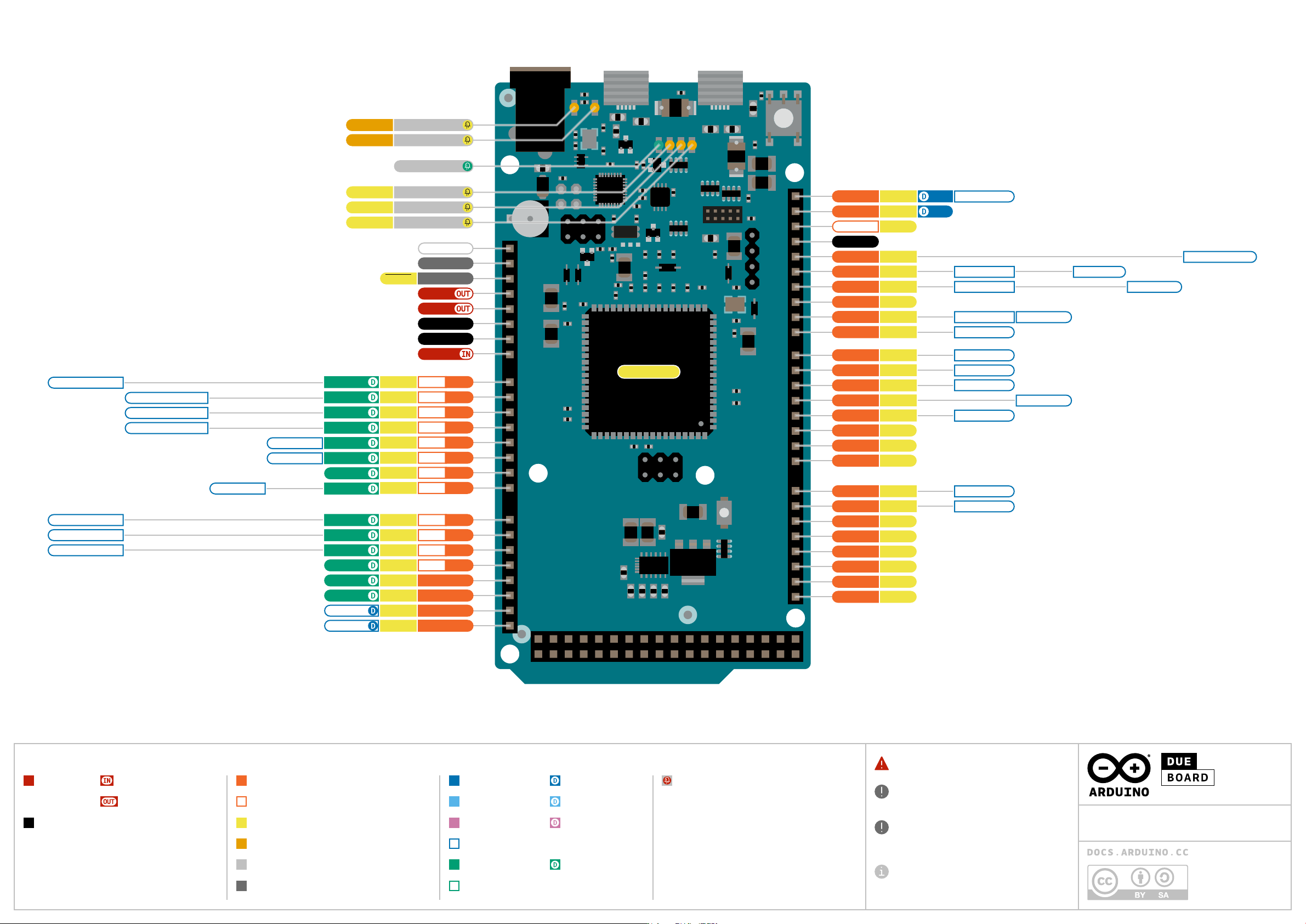
TOP VIEW
NFC
(NAND Flash
Controller)
HSMCI (High
Speed Multimedia
Card Interface)
SSC (Synchronous
Serial Controller)
NANDRDY
MCDA3
MCDA2
MCDA1
TD
RF
RD
RK
SMC (Static
Memory
Controller)
NCS0
NWAIT
External
Memory BUS
A20
A21
A17
A0
A1
A2
A3
A4
A7
A14
A15
NBS0
NRD
NANDALE
BA1
RF
SMC (Static
Memory
Controller)
NFC
(NAND Flash
Controller)
SDRAMC
(SDRAM
Controller)
SSC (Synchronous
Serial Controller)
SCL
SDA
PA18
PA17
AREF
PB27
PD8
PD7
PA28
PC21
PC22
PC23
PC24
PC25
PA29
PC28
PB25
PA9
PA8
PD4
PD5
PA13
PA12
PA11
PA10
PB12
PB13
RESET
PA16
PA24
PA23
PA22
PA6
PA4
PA3
PA2
PB17
PB18
PB19
PB20
D12
D11
D10
D9
D8
ATSAM3X8E
D7
D6
D5
D4
D3
D2
D1/TX0
D0/RX0
D14/TX3
D15/RX3
D16/TX2
D17/RX2
D18/TX1
D19/RX1
D20/SDA
D21/SCL
D21/SCL
D20/SDA
AREF
GND
D13
RXL LED
TXL LED
LED_BUILTIN
Power
RX LED
TX LED
ATMEGA16U2
PB27
PA21
PC30
PD5
PD4
PB15
PB16
PA1
PA0
RESET
D54A0
D55A1
D56A2
D57A3
D58A4
D59A5
D60A6
D61A7
D62A8
D63A9
D64A10
D65A11
IOREF
NC
GND
GND
DAC2/D66
DAC1/D67
CANRX/D68
CANTX/D69
ADC[0]
ADC[1]
ADC[2]
ADC[3]
ADC[4]
ADC[5]
ADC[6]
ADC[7]
ADC[8]
ADC[9]
ADC[10]
ADC[11]
DAC[0]
DAC[1]
VIN
+3V3
+5V
CANRX0
CANTX0
Micro
Micro
MicroAnalog/CAN
I2CMicro
This work is licensed under
the Creative Commons
Attribution-ShareAlike 4.0
International License. To view a
copy of this license, visit http://
creativecommons.org/licenses/
by-sa/4.0/ or send a letter to
Creative Commons, PO Box 1866,
Mountain View, CA 94042, USA.
SKU code: A000056
Full Pinout - Page 7 of 8
Last update: 29 Jun, 2022
To check the maximum currents
applicable per pins please
see the documentation on
DOCS.ARDUINO.CC/HARDWARE/DUE
The ADC’s channel 15 is not
available because connected to
the ATSAM3X8E temperature sensor
CIPO/COPI have previously been
referred to as MISO/MOSI
MAXIMUM current per
I/O lines is 130mA
Legend:
Power Power Input
Power Output
Ground
GPIO Digital External
Analog External
Main Part
Secondary Part
Internal Component
Other Pins (Reset, System
Control, Debugging)
I2C Default
SPI Default
UART/USART Default
Other SERIAL Communication
Analog Default
PWM/Timer
LED
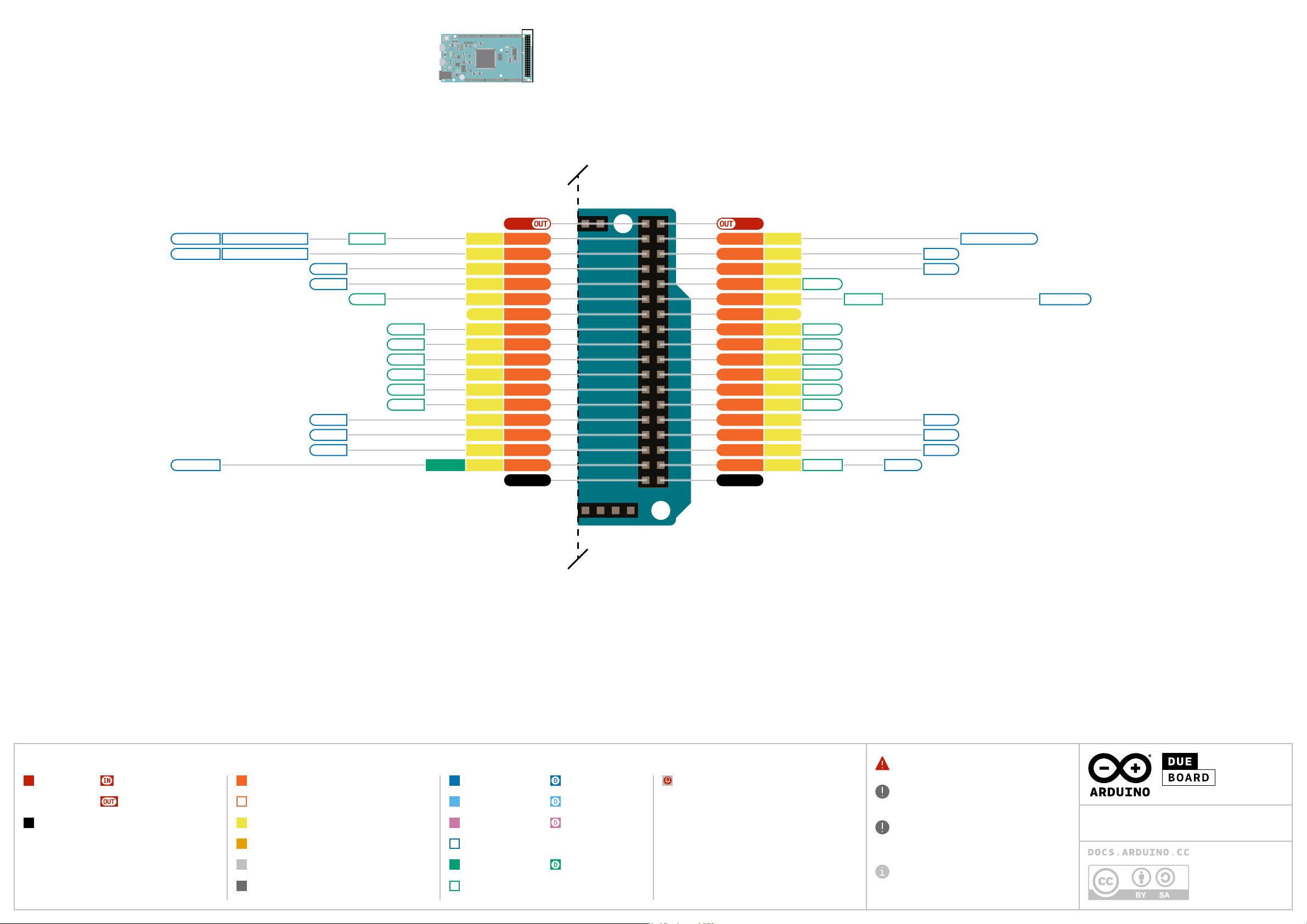
TOP
USB
Digital pins D22-D53
TOP VIEW
ANALOGPWMCOMMUNICATION ETH TIMERINTERRUPT
AD
[
14
]
PWML0
PWML1
PWML2
PWML3
PWMH1
PWMH5
CTS0
CTS1
MCDA5
MCDA7
ECOL
ETX2
ETXER
TCLK0
TCLK8
WKUP
[
15
]
WKUP
[
8
]
WKUP
[
13
]
PWM COMMUNICATIONCAN ETHTIMER INTERRUPT
PWMFI2
PWMH0
PWMH1
PWMH2
PWMH3
PWML2
PWMH6
PWMH2
RTS1
CANTX1
MCDA4
MCDA6
ETX3
ERXCK
ERX3
TCLK2 WKUP
[
3
]
D22
D24
D26
D28
D30
D32
D34
D36
D38
D40
D42
D44
D46
D48
D50
D52
GND
+5V+5V
D23
D25
D27
D29
D31
D33
D35
D37
D39
D41
D43
D45
D47
D49
D51
D53
GND
PB26
PA15
PD1
PD3
PD9
PD10
PC2
PC4
PC6
PC8
PA19
PC19
PC17
PC15
PC13
PB21
PA14
PD0
PD2
PD6
PA7
PC1
PC3
PC5
PC7
PC9
PA20
PC18
PC16
PC14
PC12
PB14
Micro Micro
This work is licensed under
the Creative Commons
Attribution-ShareAlike 4.0
International License. To view a
copy of this license, visit http://
creativecommons.org/licenses/
by-sa/4.0/ or send a letter to
Creative Commons, PO Box 1866,
Mountain View, CA 94042, USA.
SKU code: A000056
Full Pinout - Page 8 of 8
Last update: 29 Jun, 2022
To check the maximum currents
applicable per pins please
see the documentation on
DOCS.ARDUINO.CC/HARDWARE/DUE
The ADC’s channel 15 is not
available because connected to
the ATSAM3X8E temperature sensor
CIPO/COPI have previously been
referred to as MISO/MOSI
MAXIMUM current per
I/O lines is 130mA
Legend:
Power Power Input
Power Output
Ground
GPIO Digital External
Analog External
Main Part
Secondary Part
Internal Component
Other Pins (Reset, System
Control, Debugging)
I2C Default
SPI Default
UART/USART Default
Other SERIAL Communication
Analog Default
PWM/Timer
LED
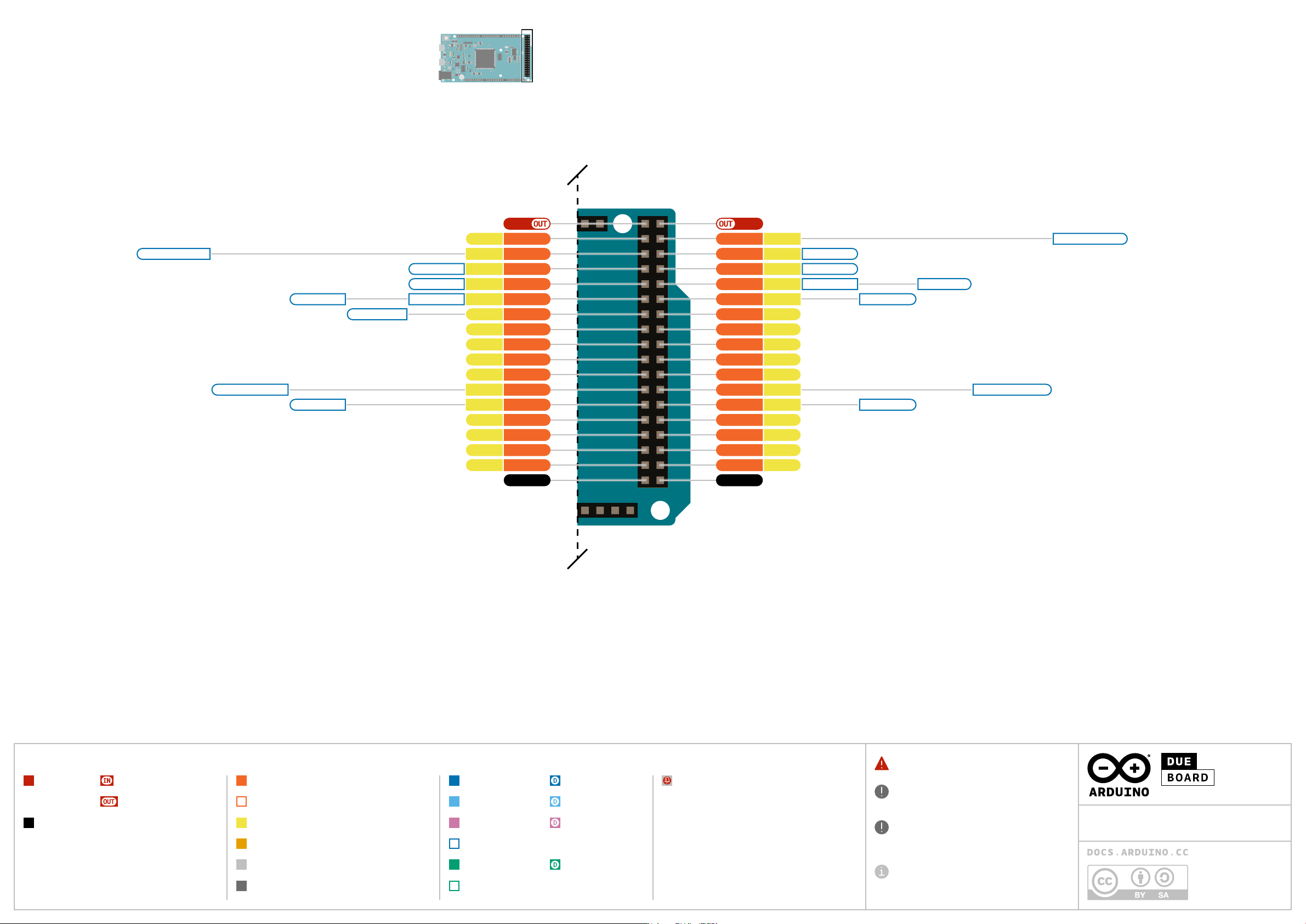
TOP
USB
Digital pins D22-D53
TOP VIEW
MCCK
TF
HSMCI (High
Speed Multimedia
Card Interface)
SSC (Synchronous
Serial Controller)
A11
A13
A22
NWR1/NBS1
NANDCLE
NANDOE
External
Memory BUS
SMC (Static
Memory
Controller)
NFC
(NAND Flash
Controller)
A10
A12
A16
NCS1
NWR0/NWE
BA0
MCCDA
TK
HSMCI (High
Speed Multimedia
Card Interface)
SSC (Synchronous
Serial Controller)
External
Memory BUS
SMC (Static
Memory
Controller)
SDRAMC
(SDRAM
Controller)
D22
D24
D26
D28
D30
D32
D34
D36
D38
D40
D42
D44
D46
D48
D50
D52
GND
+5V+5V
D23
D25
D27
D29
D31
D33
D35
D37
D39
D41
D43
D45
D47
D49
D51
D53
GND
PB26
PA15
PD1
PD3
PD9
PD10
PC2
PC4
PC6
PC8
PA19
PC19
PC17
PC15
PC13
PB21
PA14
PD0
PD2
PD6
PA7
PC1
PC3
PC5
PC7
PC9
PA20
PC18
PC16
PC14
PC12
PB14
Micro Micro