Foreign Machine Interface.pdf - 第27页
FOREIGN MACHINE INTERFACE MULTI-INTERFACE UNIT Chapter Issue 3 Jan 08 Technical Reference Manu al 28.27 SMEMA Interface SMEMA Schematic AMP Connector 206044-1 AMP Connector 206044-1 8 Shield SMEMA Downline 0V 15 25 +24V(…
FOREIGN MACHINE INTERFACE
MULTI-INTERFACE UNIT
28.26 Technical Reference Manual Chapter Issue 3 Jan 08
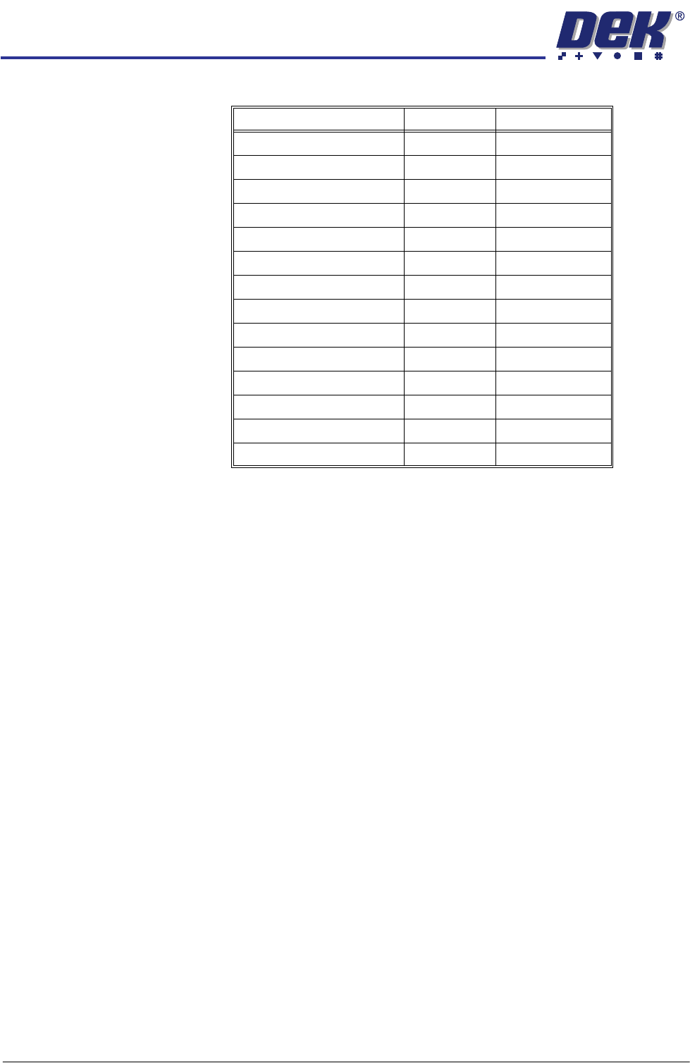
Interface Cable Part
Numbers
Transfer Period The Transfer Period in Set Preferences provides a programmable time period,
between 0 sec - 999 secs, for the following:
Period of Transfer Time - This is the period of time which the machine allows
for a transfer of a board before displaying a ‘Board Transfer Error’ for upline
or downline.
Period of Waiting Time - This is the period of time which the machine allows
when waiting for the upline or downline machine to request a board for transfer
before displaying a message of ‘Waiting for Upline/Downline’.
Protocol / Direction GA Number BOM Number
SMEMA Upline 131342 131343
SMEMA Downline 131344 131345
Siemens Upline 131334 131335
Siemens Downline 131336 131337
SMPI Upline 131330 131331
SMPI Downline 131332 131333
TDK Upline 131322 131323
TDK Downline 131324 131325
Fuji Upline 126405 126757
Fuji Downline 126406 126758
Panasonic Upline 131338 131339
Panasonic Downline 131340 131341
Sanyo Upline 142505 146120
Sanyo Downline 142504 146119
FOREIGN MACHINE INTERFACE
MULTI-INTERFACE UNIT
Chapter Issue 3 Jan 08 Technical Reference Manual 28.27
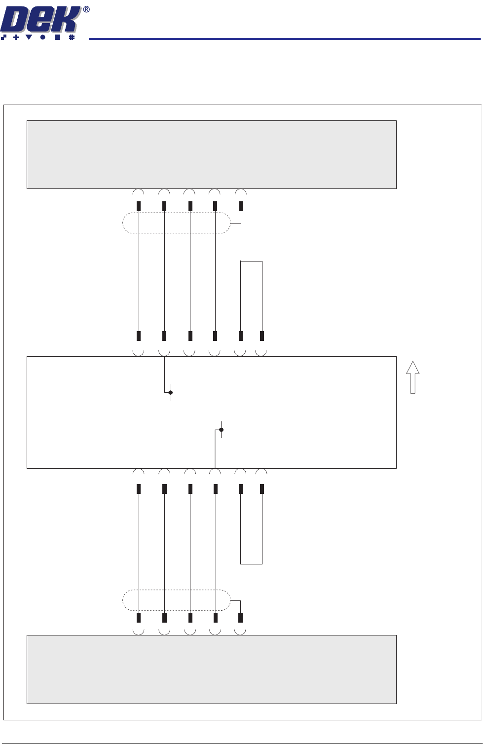
SMEMA Interface
SMEMA Schematic
AMP
Connector
206044-1
AMP
Connector
206044-1
8
Shield
SMEMA
Downline
0V
15
25
+24V(A)
Upline
50 Way
D-type
M1SK1
Downline
50 Way
D-type
M1SK2
DEK
Multi-Interface Unit
Board Direction
SMEMA FMI Connection - Upline (SW2) and Downline (SW3) To Position 2.
Out
(24V) Link
In
2
17
Machine Ready (L)
3
1
Board Available (L)
4
2
Board Available (H)
1
9
Machine Ready (H)
Shield
4
8
Board Available (L)
0V
Machine Ready (H)
1
1
2
Machine Ready (L)
2
Out
In
(24V) Link
+24V(A)
25
15
3
Board Available (H)
26
17
SMEMA
Upline
FOREIGN MACHINE INTERFACE
MULTI-INTERFACE UNIT
28.28 Technical Reference Manual Chapter Issue 3 Jan 08
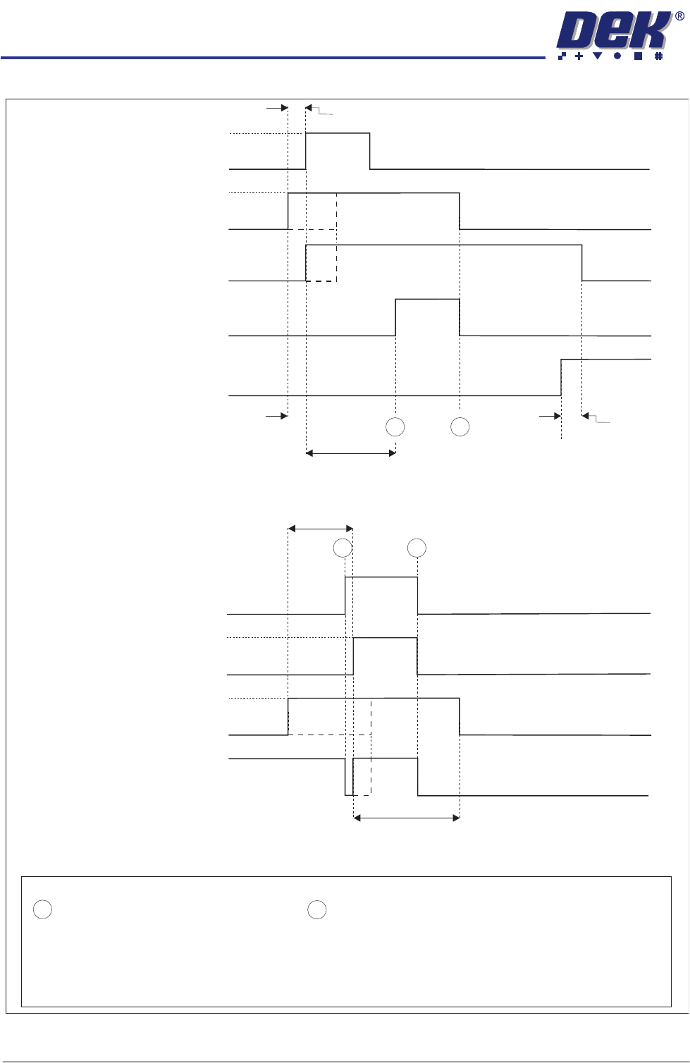
SMEMA Logical Timing Diagram
NOTES
A board transfer occurs when a board is available (contact closed) and the machine is ready (contact closed).
The Board Available signal and Machine Ready signal can occur at anytime, but board transfer does not occur
until both contacts are closed.
The Board Available signal remains closed until the board has left the machine.
The Machine Ready signal remains closed until the board has arrived at the next machine.
- Board Trailing Edge at Sensor
- Board Leading Edge at Sensor
A
B
SMEMA Downline Logical Timing Diagram
Downline M/C
(I/P to DEK M/C)
Board Not Available
Board Available
DEK M/C Belts Running
DEK M/C Output Sensor
DEK M/C
(O/P from DEK M/c)
Machine Ready
Machine Not Ready
A
B
SMEMA Upline Logical Timing Diagram
DEK M/C Input Sensor
Upline M/C
(I/P to DEK M/C)
Board Not Available
Board Available
DEK M/C
(O/P from DEK M/C)
Machine Ready
Machine Not Ready
DEK M/C Board At Stop Sensor
Board At Stop
Transfer Complete
< Transfer Period
< Transfer Period
< Transfer Period
< Transfer Period
Belt Overrun
DEK M/C Belts Running
A
B
DEK M/C Ready