Nordson-EFD-741MD-Maintenance-Guide.pdf - 第4页
741MD-SS Needle Valve | Maintenance & Parts Guide For Nordson EFD sales and service in over 40 countries, contact Nordson EFD or go to www.nordsonefd.com. Global 800-556-3484; +1-401-431-7000 info@nordsonefd.com Euro…
741MD-SS Needle Valve | Maintenance & Parts Guide
2 www.nordsonefd.com info@nordsonefd.com +1-401-431-7000 Sales and service of Nordson EFD dispensing systems are available worldwide.
Valve Disassembly and
Reassembly Procedures
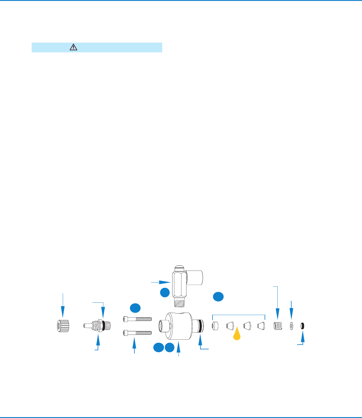
To prevent damage, the valve must be disassembled
starting at the fluid outlet end of the valve.
CAUTION
Valve Maintenance
To thoroughly clean the fluid body and replace needle
packings:
1. Remove the inlet fitting and tip adapter.
2. Remove the fluid body from the air cylinder body,
then remove the O‑ring.
3. Use tool #7021552 to remove the needle
packings from the fluid body.
4. Remove any remaining packings and remove the
spring from the needle.
5. Clean the needle with a cloth dampened in
solvent and lubricate with the Nye Lubricant
#865 gel included in the General Maintenance
Kit. Lubricate and reinstall the needle packing
assembly.
6. Install the new, lubricated O‑ring on the fluid
body. Then install the chamber in the air cylinder
body.
7. Turn the fluid body to position the fluid inlet
hole in the desired location. Install and tighten
the fluid body mounting screws (2). Torque to
1.58N•m (14in‑lb).
8. Reinstall the tip adapter / seat assembly.
Retaining nut only
#7021194
Inlet fitting
#7021867
Needle packing assembly
#7007014
Tip adapter with
retaining nut #7021227
(2) Body mounting
screws #7023632
O‑ring
#7018502
(Buna‑N)
Fluid body
#7021252 (stainless steel)
Nye gel lubricant, 1 gram
foil packet (not shown)
#7014917
Packing spring
#7014683
1
2
7
6
3
O‑ring #7014718
O‑ring #7014684
Retaining
washer
#7014685
741MD-SS Needle Valve | Maintenance & Parts Guide
3www.nordsonefd.com info@nordsonefd.com +1-401-431-7000 Sales and service of Nordson EFD dispensing systems are available worldwide.
Maintenance Tools:
6" adjustable wrench
Snap‑ring pliers
Packing extraction tool #7021552
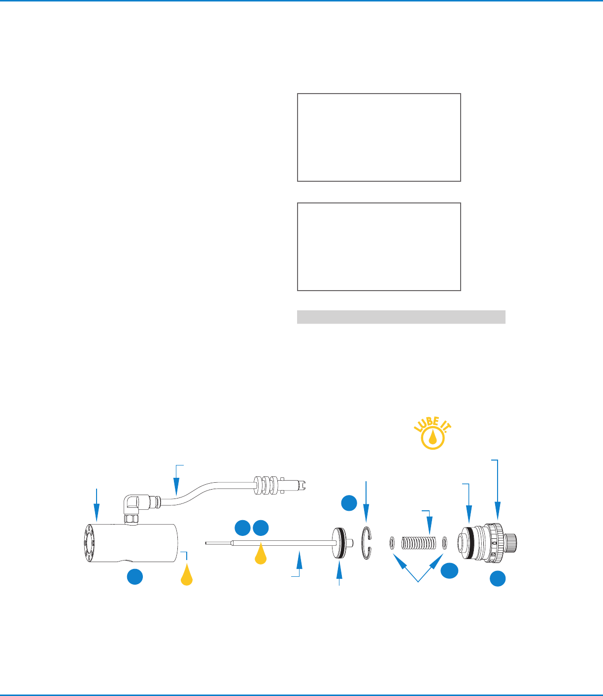
Air cylinder body
#7021245
Piston‑and‑needle
assembly #7007008
Air input hose #7007036
Piston
return spring
#7014682
9
5
11
10
12
Replacing the Piston and Needle
Assembly or Piston O‑Ring
9. Remove the needle stroke control knob.
10. Remove the piston return spring and thrust
washers.
11. Remove the snap ring.
12. With small pliers on the spring pilot, pull the
piston‑and‑needle assembly out of the air
cylinder body. The piston‑and‑needle assembly
is one unit and cannot be disassembled.
13. Clean the air cylinder body wall and replace the
piston O‑ring. Lubricate with the Nye Lubricant
#865 gel included in the General Maintenance
Kit.
14. Reassemble the valve in the reverse order of
disassembly.
NOTE: Ensure that the lower cylinder needle
O‑ring is back in place before reinstalling the
packing spring.
Stroke calibration knob
#7021267
Snap ring
#7014757
Thrust washer
#7014862
O‑ring
#7014687
13
General Maintenance Kit
#7007030
Includes all O‑rings, needle packing
set, and foil pack of Nye Lubricant
#865 gel.
Valve Disassembly and
Reassembly Procedures
(continued)
O‑ring #7014686
Part # Description
7021233
741MD‑SS Valve

741MD-SS Needle Valve | Maintenance & Parts Guide
For Nordson EFD sales and service in over
40 countries, contact Nordson EFD or go to
www.nordsonefd.com.
Global
800-556-3484; +1-401-431-7000
info@nordsonefd.com
Europe
00800 7001 7001
infoefd.europe@nordsonefd.com
Asia
China: +86 (21) 3866 9006; china@nordsonefd.com
India: +91 80 4021 3600; india@nordsonefd.com
Japan: +81 03 5762 2760; japan@nordsonefd.com
Korea: +82-31-736-8321; korea@nordsonefd.com
SEAsia: +65 6796 9522; sin-mal@nordsonefd.com
The Wave Design is a trademark of Nordson Corporation.
©2024 Nordson Corporation 7026831 v030724
Troubleshooting Guide
No fluid flow
• If the valve operating air pressure is too low, the
valve will not open. Increase the air pressure to
4.8bar (70psi) minimum.
• The reservoir air pressure may not be high enough.
Increase the pressure.
• The needle stroke adjustment may be closed.
Open the stroke adjustment.
• Material may have clogged the fluid body or output
tip adapter. Clean the valve.
• The dispensing tip retaining nut may not have been
tightened enough to unseat the needle. Tighten the
nut.
Steady Drip
• Remove the tip adapter / seat assembly. Clean and
inspect the needle. Replace the dispensing tip.
• Make sure tip size is not larger than 22 gauge.
Fluid leaks out the drain hole
• Fluid leaking out the drain hole on the side of the
valve indicates that the needle packings are worn.
Replace the needle packings.
Inconsistent deposits
• Inconsistent deposits can result if the air pressure
controlling the valve and / or supplying the
reservoir is fluctuating or if the valve operating
pressure is less than 4.8bar (70psi). Check to be
sure air pressures are constant and that the valve
operating pressure is 4.8bar (70psi).
• The time the valve is open must be constant.
Check to be sure that the valve controller is
providing a consistent output.
Calibration Feature
The stroke control reference ring of each 741MD‑SS
valve is factory calibrated to zero position. Slight
internal variations in dispensing tips may require the
stroke control to be recalibrated when tips are changed.
To do so:
1. Make a note of the current stroke setting number.
2. Turn the calibration knob (inner) counterclockwise
one full turn.
3. Install the new dispensing tip and ensure that the
retaining nut is tightened fully.
4. Turn the stroke adjustment knob (outer) clockwise
until it stops at the zero position.
5. Turn the calibration knob clockwise until it stops.
The stroke adjustment is now calibrated to zero.
6. Reset stroke to the required position noted in
step1.
Calibration Feature
(continued)
In the event that the stroke reference ring must be
repositioned or reset to the zero mark, use the following
procedure:
A. Remove the dispensing tip, if installed.
B. Turn the small knob counterclockwise one full turn.
C. Turn the large knob clockwise until it stops.
If the zero on the reference ring does not line‑up with
the index mark, continue with the following steps:
D. Loosen the small set screw located on the
reference ring.
E. Rotate the reference ring until it aligns with the
reference line on the air cylinder body.
F. Tighten the small set screw to lock the reference
ring into position.
G. Install a dispensing tip and follow calibration
procedure steps 3 to 5.