00193365-0202.pdf - 第30页
Item no. / Artikel-Nr.: 00193365-0202 A SM Assembly Systems GmbH & Co. KG Rupert-Mayer-Strasse 44 81379 München Germany www.siplace.com
Retrofit instructions Splice sensors 8 - 72 mm
07/2003 Edition
28
Install Splice Detect Sensor on Feeder 4
: Attach the Splice Detect Sensor Spring with the (2) saved m3 x 4 flat head screws to the remo-
ved spring mount bracket.
: Slide the bracket back into the feeder until the end slot engages the pins inside of the feeder
where it was originally attached.
Use the saved phillips head screws to attach the bracket on both sides of the feeder. The Splice
Detect Sensor is now installed.
Install Feeder 4
: Re-install completed feeder module onto feeder table at original machine location.
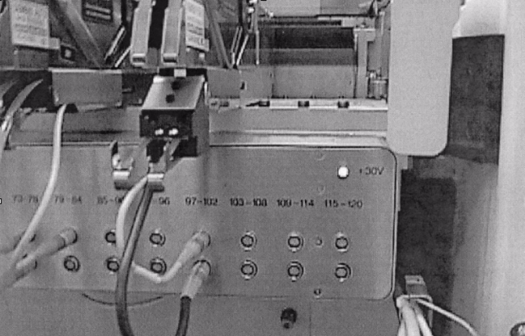
: Re-plug feeder communication cable into feeder communication unit and plug splice detect
sensor communication cable into unit as shown in Fig. 4 - 6.
4
Fig. 4 - 6 Communication cables installed
The installation is now complete. Refer to Splice Detect Sensor operations instructions for further
information. 4
4
LEDs on splice sensors 4
The LEDs on the splice sensors have the following meaning: 4
– LED on: Ready
– LED off: Splice detected
4

Item no. / Artikel-Nr.: 00193365-0202 ASM Assembly Systems GmbH & Co. KG
Rupert-Mayer-Strasse 44
81379 München
Germany
www.siplace.com