ZFBT-6GW+_dashboard.pdf - 第4页
B i as T ee , C o ax i al ZF B T - 6 G W+ T y p i c a l P er f or m an c e C ur v es I n se r t ion Lo ss 0 .0 0 .2 0 .4 0 .6 0 .8 1 .0 1 .2 1 .4 1 .6 1 .8 2 .0 0 500 1000 1500 2000 2500 3000 3500 4000 4500 5000 5500 600…
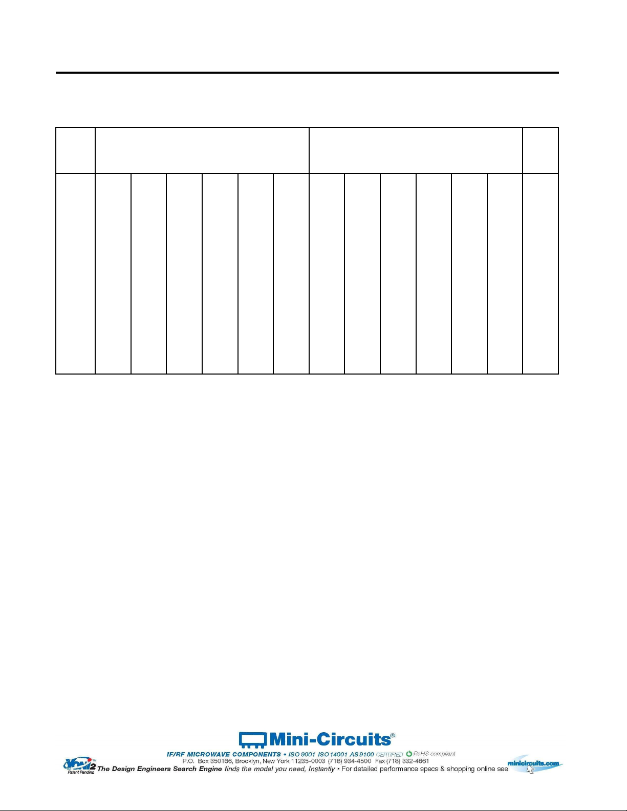
Bias Tee, Coaxial ZFBT-6GW+
Typical Performance Data
(MHz)
(:1)
0.10
0.17
0.17
0.16
0.17
0.20
0.24
19.46
19.04
17.83
14.58
12.66
11.75
1.16
0.27
0.13
0.13
0.13
0.14
0.14
0.15
25.86
25.53
24.52
21.43
19.31
18.16
1.07
0.53
0.12
0.12
0.12
0.11
0.11
0.11
29.17
28.98
28.36
26.18
24.40
23.37
1.04
1.06
0.13
0.13
0.12
0.11
0.12
0.12
30.81
30.74
30.56
29.62
28.62
27.92
1.02
10.00
0.16
0.17
0.17
0.16
0.16
0.16
30.06
30.07
30.07
30.20
30.38
30.56
1.04
114.75
0.22
0.25
0.24
0.22
0.22
0.22
34.45
34.49
34.27
33.99
33.83
33.59
1.07
324.25
0.50
0.55
0.53
0.52
0.53
0.56
44.65
44.61
44.25
43.90
43.91
43.34
1.06
743.25
0.28
0.31
0.30
0.29
0.29
0.29
51.19
50.50
50.16
50.65
51.69
52.47
1.06
952.75
0.31
0.33
0.33
0.31
0.32
0.33
40.75
40.80
40.97
40.97
40.93
40.95
1.11
1581.25
0.46
0.48
0.47
0.46
0.48
0.49
42.58
42.59
43.94
43.77
44.36
44.17
1.13
2000.25
0.46
0.48
0.47
0.46
0.46
0.47
45.46
45.57
45.73
45.48
46.14
45.28
1.12
2524.00
0.40
0.42
0.41
0.42
0.43
0.44
53.15
53.72
52.19
53.17
52.67
53.67
1.12
3047.75
0.45
0.48
0.47
0.46
0.46
0.49
52.46
52.25
51.55
51.33
51.46
50.99
1.09
3676.25
0.73
0.74
0.75
0.75
0.75
0.75
46.32
47.19
46.36
45.53
46.19
45.65
1.07
4200.00
1.04
1.07
1.07
1.06
1.05
1.06
28.42
28.36
28.24
28.14
28.01
27.92
1.09
4502.50
1.17
1.19
1.18
1.19
1.17
1.16
28.15
28.10
28.05
27.96
27.84
27.87
1.14
4802.00
1.26
1.26
1.27
1.25
1.22
1.20
37.95
38.01
38.19
37.93
37.58
37.51
1.12
5251.75
1.19
1.17
1.16
1.13
1.11
1.09
49.68
51.04
49.12
49.37
49.13
48.19
1.11
5550.75
1.65
1.63
1.60
1.56
1.54
1.51
38.44
38.56
38.36
38.07
37.85
38.19
1.10
6000.00
1.70
1.71
1.65
1.59
1.54
1.50
34.37
34.36
34.23
34.40
34.49
34.48
1.12
150mA 200mA
INSERTION LOSS with current
(RF Port to RF&DC Port)
FREQ.
(dB)
0mA 20mA 50mA 100mA
VSWR
ISOLATION with current
(RF Port to DC Port, RF&DC Port to DC Port)
(dB)
10mA 20mA 50mA 100mA 150mA 200mA
REV. X1
ZFBT-6GW+
070717
Page 1 of 1
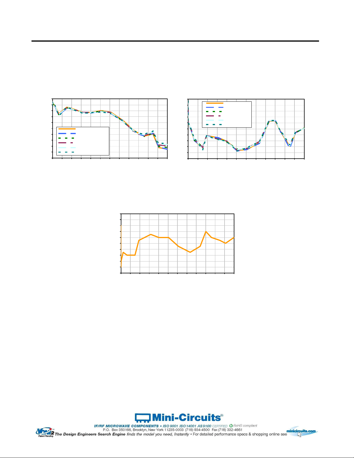
Bias Tee, Coaxial ZFBT-6GW+
Typical Performance Curves
Insertion Loss
0.0
0.2
0.4
0.6
0.8
1.0
1.2
1.4
1.6
1.8
2.0
0 500 1000 1500 2000 2500 3000 3500 4000 4500 5000 5500 6000
Frequency (MHz)
Insertion Loss (dB)
Insertion Loss @0mA
Insertion Loss @20mA
Insertion Loss @50mA
Insertion Loss @100mA
Insertion Loss @150mA
Insertion Loss @200mA
Isolation
10
15
20
25
30
35
40
45
50
55
60
0 500 1000 1500 2000 2500 3000 3500 4000 4500 5000 5500 6000
Frequency (MHz)
Isolation (dB)
Isolation @10mA
Isolation @20mA
Isolation @50mA
Isolation @100mA
Isolation @150mA
Isolation @200mA
VSWR
1.00
1.02
1.04
1.06
1.08
1.10
1.12
1.14
1.16
1.18
1.20
0 500 1000 1500 2000 2500 3000 3500 4000 4500 5000 5500 6000
Frequency (MHz)
VSWR
REV. X1
ZFBT-6GW+
070717
Page 1 of 1
K18 Rev.: G (05 MAY 21) ECO-007134 File: K18 Sheet 1 of 1
This document and its contents are the property of Mini-Circuits
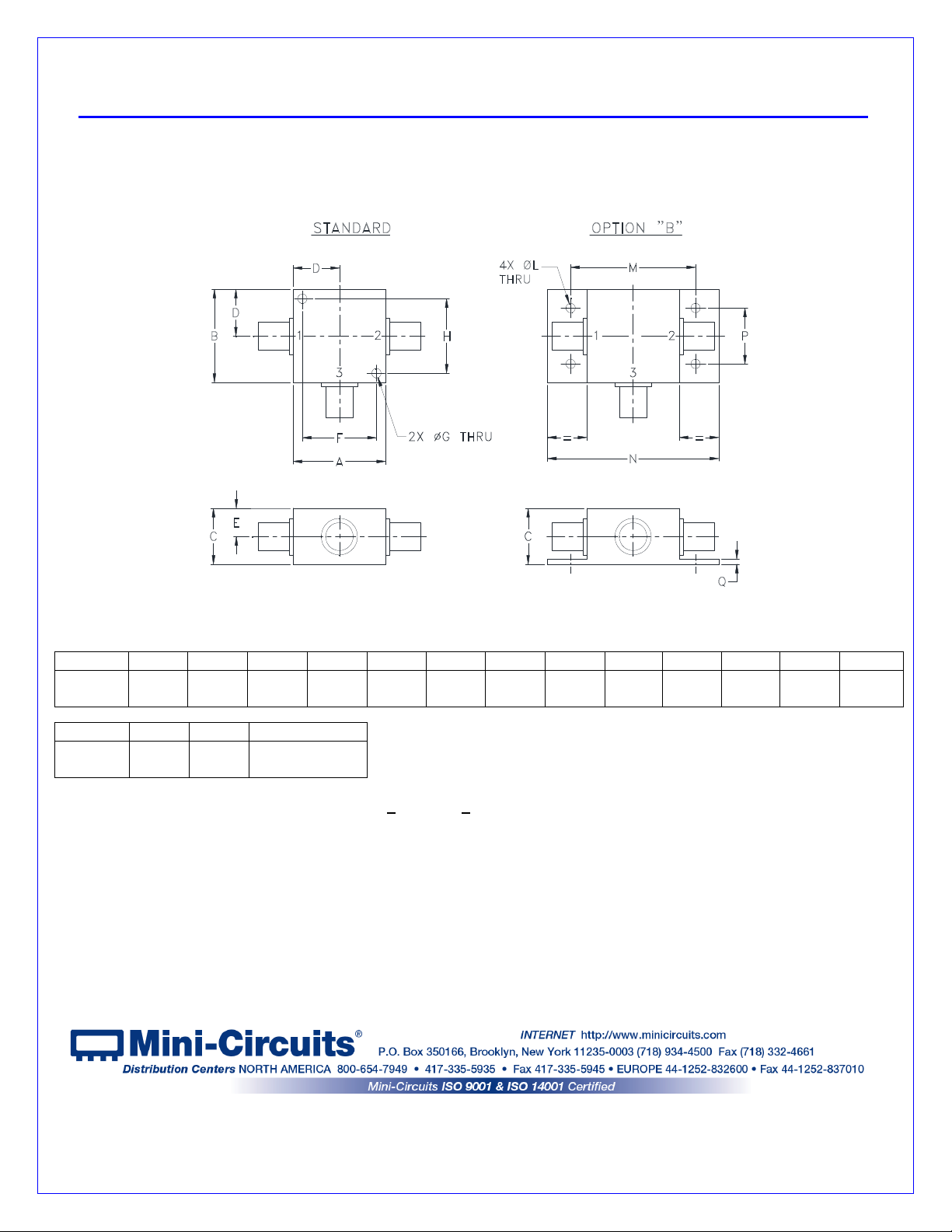
Case Style K
Notes:
1. Case material: Aluminum alloy.
2. Case finish:
For RoHS Case Styles: Clear chemical conversion coating, non-chrome or trivalent chrome based.
3. Mounting bracket available on request. Add suffix B to part number.
4. For port marking 1, 2, and 3 see specifications data sheet.
5.
For bracket version, option B, dimension “C” changes from .75 to .94 inches when connectors are type N.
6.
Refer to the individual model data sheet for the type of connectors available.
CASE# A B C D E F G H J K L M N
K18
1.25
(31.75
1.25
(31.75)
.75
(19.05)
.63
(16.00)
.38
(9.65)
1.000
(25.40)
.125
(3.18)
1.000
(25.40)
--
--
--
--
.125
(3.18)
1.688
(42.88)
2.18
(55.37)
CASE# P Q WT. GRAMS
K18
.75
(19.05)
.07
(1.78)
70.0
Dimensions are in inches (mm). Tolerances: 2 Pl. + .03; 3 Pl. + .015
Outline Dimensions
K18